MICROSERIES1402-VLZ MIC/LINE MIXER OWNER’S MANUAL TM PHANTOM POWER CAUTION WARNING: MAIN RIGHT MAIN LEFT BALANCED BALANCED ALT 3-4 OUTPUT CONTROL ROOM 120 VAC 50/60 Hz 25W 315mA/250V SLO-BLO CAUTION: CHANNEL INSERTS BAL/UNBAL BAL/UNBAL PRE-FADER / PRE EQ ( TIP SEND / RING RETURN) MAIN OUTPUT LEVEL TO REDUCE THE RISK OF FIRE REPLACE WITH SAME TYPE FUSE AND RATING CONCEIVED, DESIGNED, AND MANUFACTURED BY MACKIE DESIGNS INC.
CAUTION AVIS RISK OF ELECTRIC SHOCK DO NOT OPEN RISQUE DE CHOC ELECTRIQUE NE PAS OUVRIR CAUTION: TO REDUCE THE RISK OF ELECTRIC SHOCK DO NOT REMOVE COVER (OR BACK) NO USER-SERVICEABLE PARTS INSIDE REFER SERVICING TO QUALIFIED PERSONNEL ATTENTION: POUR EVITER LES RISQUES DE CHOC ELECTRIQUE, NE PAS ENLEVER LE COUVERCLE. AUCUN ENTRETIEN DE PIECES INTERIEURES PAR L'USAGER. CONFIER L'ENTRETIEN AU PERSONNEL QUALIFIE.
READ THIS PAGE!!! We realize that you must be dying to try out your new MicroSeries 1402-VLZ. Or you might be one of those people that never read manuals. Either way, all we ask is that you read this page NOW, and the rest can wait until you’re good and ready. But do read it — you’ll be glad you did. LEVEL-SETTING PROCEDURE Message to seasoned pros: do not set levels using the old “Turn the trim up until the clip light comes on, then back off a hair” trick.
INTRODUCTION Thank you! There are a lot of makes and models of compact mixers out there, all competing for your bucks… but you have voted with your wallet for the folks in Woodinville who specialize in American-made mixers. Now that you have your MicroSeries 1402-VLZ, find out how to get the most from it. That’s where this manual comes in.
CONTENTS LEVEL-SETTING PROCEDURE ............................ 3 HOOKUP DIAGRAMS ....................................... 6 PATCHBAY DESCRIPTION ............................... 10 MIC INPUTS ............................................ 10 PHANTOM POWER .................................. 10 LINE INPUTS ........................................... 11 LOW CUT ................................................ 11 TRIM ...................................................... 11 +4 / –10 ................................
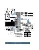
HOOKUP DIAGRAMS 4-track Recorder out (play) in (record) IMPORTANT: ALL Channel Insert plugs are inserted to the SECOND click.
V/O Mic in Compressor 1 1 1 out 3 4 5 Audio out 10 R 11 L MONO 12 R CD Player L L 13 MONO 14 R L R R 1 L 2 in CNTRL ROOM OUTPUTS R L Note: Aux Return #2 can be used as an extra stereo input ,, , R L R Power Amplifier FULL SYMMETRY DUAL DIFFERENTIAL HIGH CURRENT DESIGN CH CH 1 2 OL OL PWR PWR ON HIGH RESOLUTION STUDIO MONITOR Mackie Designs: Video Setup scene #1 _ 23:94:10 Time Base out Multi Effect Processor in OUT L out R R L PHONES Time code DAT L IN-TAPE-
in 1 1 Stereo Compressor out 1 in CHANNEL INSERTS 2 Turntable 3 1 4 Phono Preamps 5 3 2 out 3 out in 4 6 6 4 R CD Player L out L 11 MONO 12 R out 14 R in L 2-track Deck R L 1 L R R Triggered Lights org in 2 Multi Effect Processor out L Stereo EQ OUT CNTRL ROOM OUTPUTS in (record) Power Amplifier red FULL SYMMETRY DUAL DIFFERENTIAL HIGH CURRENT DESIGN CH 1 CH 2 red Left PA Speaker People dancing on the floor MS1402-VLZ Disc Jockey Setup 8 in out PHO
Vocal Mics 1 3 4 4 5 5 2 CHANNEL INSERTS 2 1 in out in out 1 Stereo Compressor 3 in Mono Compressor out 4 5 Bass Preamp 6 6 Stereo Guitar Effects L MONO org org INPUTS 10 R L 11 MONO 12 R AUX RETURNS 9 Keyboard or other line-level input L 1 R 2 L R out AUX OUT Drum Machine CHANNEL MONO 8 R 1 ALT 3/4 OUT 7 L L 2 in L 13 MONO Power Amp Mono EQ out R ,,, 14 R Multi Effect Processor in FULL SYMMETRY DUAL DIFFERENTIAL HIGH CURRENT DESIGN MAIN OUT R CH 2 L
MS1402-VLZ PATCHBAY DESCRIPTION Professional ribbon, dynamic and condenser mics will all sound excellent through these inputs. The MS1402-VLZ’s mic inputs will handle any kind of mic level you can toss at them, without overloading. Be sure to perform the Level Setting Procedure: . At the risk of stating the obvious, this is where you plug everything in: microphones, line-level instruments and effects, headphones, and the ultimate destination for your sound: a tape recorder, PA system, etc.
LINE INPUTS (Channels 1–6) These six line inputs share circuitry (but not phantom power) with the mic preamps, and can be driven by balanced or unbalanced sources at almost any level. You can use these inputs for virtually any signal you’ll come across, from instrument levels as low as –30dB to operating levels of –10dBV to +4dBu, since there is 30dB more gain available than on Channels 7–14. To learn how signals are routed from these inputs: .
MIC 1 MIC 4 MIC 3 MIC 2 MIC 5 MIC 6 STEREO AUX RETURNS 1 TAPE INPUT AUX SEND 1 TAPE OUTPUT MAIN OUTS L L R 2 2 R LEFT (1/MONO) LINE IN 2 LINE IN 1 -10dGBAV MIC IN -10dGBAV MIC IN U 10 +10dB 60 -40dB 60 -40dB U 10 +10dB 60 -40dB LOW CUT 75 Hz 18dB/OCT -10dGBAV MIC IN 60 -40dB 10 +10dB TRIM 60 -40dB TRIM Dry Signal Aux Send Parallel 12 L L L MONO L BAL OR UNBAL BAL OR UNBAL BAL OR UNBAL BAL OR UNBAL R R R R LEVEL +4 -10 LEVEL +4 -10 LINE IN 9–10 Parallel Devi
INSERT (Channels 1–6) WARNING: These jacks, on the back of the MicroSeries 1402-VLZ, are where you connect serial effects such as compressors, equalizers, de-essers, or filters . Since most people don’t have more than a few of these gadgets, we’ve included inserts for just the first six channels. If you want to use this kind of processing on Channels 7–14, simply patch through the processor before you plug into the MS1402-VLZ.
MIC 1 MIC 4 MIC 3 MIC 2 MIC 5 STEREO AUX RETURNS 1 MIC 6 TAPE OUTPUT TAPE INPUT AUX SEND 1 MAIN OUTS L L R 2 2 R LEFT (1/MONO) LINE IN 2 LINE IN 1 -10dGBAV MIC IN U 60 -40dB TRIM 60 -40dB TRIM 60 -40dB TRIM 60 -40dB TRIM LINE IN 6 LOW CUT 75 Hz 18dB/OCT -10dGBAV MIC IN U 10 +10dB BAL OR UNBAL LOW CUT 75 Hz 18dB/OCT -10dGBAV MIC IN U 10 +10dB LINE IN 5 LOW CUT 75 Hz 18dB/OCT -10dGBAV MIC IN U 10 +10dB LINE IN 4 LOW CUT 75 Hz 18dB/OCT -10dGBAV MIC IN U 10 +10dB LINE IN
MAIN OUTPUT LEVEL For most music recording and PA applications, unbalanced lines are perfectly acceptable. To use these outputs to drive unbalanced inputs, connect 1⁄4" TS (Tip-Sleeve) phone plugs like this: Engaging this switch pads the balanced XLR MAIN OUTPUTS by 30dB, so you can feed the microphone input of, say, another mixer. Perfect for sending a submix to another mic level input in boardroom or conference room applications.
MIC 1 MIC 4 MIC 3 MIC 2 MIC 5 STEREO AUX RETURNS 1 MIC 6 TAPE INPUT AUX SEND 1 TAPE OUTPUT MAIN OUTS L L R 2 2 R LEFT (1/MONO) BAL OR UNBAL BAL OR UNBAL LINE IN 2 LINE IN 1 -10dGBAV MIC IN U 10 +10dB 60 -40dB TRIM -10dGBAV MIC IN 60 -40dB TRIM U 10 +10dB LINE IN 5 60 -40dB 60 -40dB TRIM LOW CUT 75 Hz 18dB/OCT -10dGBAV MIC IN RIGHT BAL/UNBAL ALL BAL/UNBAL MONO MONO MONO L L L MONO L BAL OR UNBAL BAL OR UNBAL BAL OR UNBAL BAL OR UNBAL R R R LEVEL +4 -10 LEVEL
POWER CONNECTION POWER SWITCH Just in case you lose the cord provided with the MS1402-VLZ, its power jack accepts a standard 3-prong IEC cord like those found on most professional recorders, musical instruments, and computers. At the other end of our cord is — get this — a plug! Not a black cube or, as we’re fond of calling them, a “wall wart.” We did this for some very good reasons: The MS1402-VLZ has sophisticated power requirements that a wall wart cannot provide.
CHANNEL STRIP DESCRIPTION AUX 1 U MON/ EFX +15 OO U 2 EFX +15 OO EQ U HI 12kHz -15 +15 U MID 2.5kHz -12 +12 U LOW 80Hz -15 +15 PAN L The ten channel strips look alike, and function identically. The only difference is that the six on the left are for individual mics or mono instruments and have more gain available, while the next four are for either stereo or mono line-level sources. (Each of the stereo channel strips is actually two complete circuits.
and PHONES outputs. If you want the ALT 3–4 signals to go back into the MAIN MIX, engage the ASSIGN TO MAIN MIX switch , and the CONTROL ROOM/PHONES fader becomes the one fader to control the levels of all channels assigned to ALT 3–4. Another way to do the same thing is to assign the channels to the ALT 3–4 mix, then patch out of the ALT OUT LEFT and RIGHT back into an unused stereo channel (7–8, 9–10 or 11–12 or 13–14).
AUX 1 U MON/ EFX +15 OO U 2 EFX +15 OO EQ U HI 12kHz -15 +15 U MID 2.5kHz -12 +12 U LOW 80Hz -15 +15 PAN L With EQ, you can also screw things up royally. We’ve designed a lot of boost and cut into each equalizer circuit, because we know everyone will occasionally need that. But if you max the EQs on every channel, you’ll get mix mush. Equalize subtly and use the left sides of the knobs (cut), as well as the right (boost).
OUTPUT SECTION DESCRIPTION Still with us? Good for you. Here come the tricky parts, where the mixing is really done. MAIN MIX As the name implies, this fader controls the levels of signals sent to the MAIN OUTPUTS: XLR , 1⁄4" and RCA TAPE OUT . All channels and AUX RETURNS that are not muted or turned fully down will wind up in the MAIN MIX. Fully down is off, the “U” marking is unity gain, and fully up provides 10dB additional gain.
Now you know how to select the signals you want to send to the engineer’s control room or phones. From there, these signals all pass through the same level control, aptly named: CONTROL ROOM / PHONES As you might expect, this fader controls the levels of both the stereo CONTROL ROOM OUTPUTS and PHONES OUTPUTS . The control range is from off through unity gain at the “U” marking, with 10dB of extra gain fully up.
ASSIGN TO MAIN MIX Let’s say you’re doing a live show. Intermission is nearing and you’ll want to play a soothing CD for the crowd to prevent them from becoming antsy. Then you think, “But I have the CD player plugged into the TAPE inputs, and that never gets to the MAIN OUTPUTS!” Oh, but it does. Simply engage this switch and your SOURCE matrix selection, after going through the CONTROL ROOM / PHONES fader, will feed into the MAIN MIX, just as if it were another stereo channel.
AUX 1 SELECT AUX TALK First of all, there is no particular alliance between AUX SEND 1 (or 2) and AUX RETURN 1 (or 2). They’re just numbers. They’re like two complete strangers, both named Fred. Here’s the whole idea behind sends and returns: sends are outputs, returns are inputs. AUX SENDs tap signals off the channels, via their AUX knobs , mix these signals, then send them out via the AUX SEND jacks . These outputs are fed to the inputs of a reverb or other device.
Signals passing through the AUX RETURN level controls will proceed directly to MAIN MIX , with one exception (see next paragraph). The AUX RETURNS do not have MUTE/ALT 3-4 switches, so if you want these signals to get to the ALT 3-4 mix, you’ll have to patch the effects device’s outputs into one of the stereo channels, and MUTE/ ALT that channel . EFX TO MONITOR The idea behind this great feature is simple: If you want to add reverb or delay to the stage monitor mixes, this is the switch for you.
MODIFICATIONS For most folks, the MS1402-VLZ works just fine the way it is. But for special applications, there are three signal routing changes that can be performed easily on the MS1402-VLZ. Easy for someone with soldering experience, that is. If you don’t know how to solder, find a technician that can. This is NOT a good place to learn! • Modification A changes AUX SEND 2 to be pre-fader, pre-mute instead of post-fader, post-mute.
1. PRE-FADER MOD (AUX TO MONITOR) This modification changes AUX SEND 2 to be pre-fader, pre-mute instead of post-fader, post-mute. (“Mute” refers to the channel’s MUTE/ALT 3–4 switch.) In order to convert the entire mixer, it must be done on each channel, and is slightly more involved for the stereo channels 7–14. The work area is on the underside of the circuit board, near the channel AUX SEND knobs. 1. Remove all cords, including the power cable, from the MS1402-VLZ. 2.
2. PRE-MUTE MOD This modification changes AUX SEND 1 (in post mode) and AUX SEND 2 to receive signal regardless of the channel’s MUTE/ALT 3–4 switch position, but still be post-fader. In order to convert the entire mixer, it must be done on each channel, and is slightly more involved for the stereo channels 7–14. The work area is on the underside of the circuit board, near the channel MUTE/ALT 3–4 switches. 1. Remove all cords, including the power cable, from the MS1402-VLZ. 2.
3. MAIN MIX SOURCE MOD This modification changes the SOURCE matrix’s MAIN MIX selection to tap the stereo signal before the MAIN MIX level control (pre) instead of after (post). This could be especially handy for live work where the engineer wants to be able to control the MAIN MIX level (sent to the house system) without changing the level in his headphones. The work area is on the underside of the circuit board, near the MAIN MIX level control.
MUTE / ALT PAN FADER TRIM 1 MIC IN 75Hz HPF 3 1 HI 2 80 2K5 12K 3 LO 2 MID LOW CUT 4 SIP L 3-BAND EQ LINE IN SIP R SOLO PFL LOGIC AUX SEND 2 POST PRE MONO CHANNEL (1 OF 6) AUX SEND 1 FADER LO MID HI MUTE / ALT LINE IN L 1 80 2K5 12K 2 PAN +4 /-10 3 4 LO MID HI LINE IN R 80 2K5 12K SIP L 3-BAND EQ SIP R SOLO PFL LOGIC AUX SEND 2 POST PRE STEREO CHANNEL (1 OF 4) AUX SEND 1 L IN (MONO) AUX RETURN 1 GAIN R IN L IN AUX RETURN 2 MACKIE MS1402-VLZ SIGNAL FLOW-- INPUTS (M
SIP L SIP R SOLO/PFL LOGIC AUX 1 PRE AUX 1 POST AUX 2 POST MAIN L MAIN R ALT L ALT R TAPE OUT L LINE OUT L 2 BAL OUT L 1 3 MAIN MIX 30dB PAD MAIN FADERS 2 BAL OUT R 1 3 LINE OUT R ALT OUT L TAPE OUT R ALT OUT R ALT MIX METERING (0dBu = 0VU) ALT SOURCE TAPE IN L 22 10 7 4 2 0 2 4 7 10 20 30 TAPE R CONTROL ROOM & PHONES MIX RUDE SOLO LED MAIN SOLO RELAY SIP L SIP R PFL PFL LED SOLO MIX SIP (SOLO IN PLACE) / PFL (PRE-FADER LISTEN) CONTROL ROOM LEFT ASSIGN TO MAIN PHONES OUT CONTROL RO
0dB +12dB engaged 0dB 0dB to ‘A’ to ‘A’ to ‘A’ ‘A’ LINE IN, Channels 5–12 +4 (dBu) / –10 (dBV) Unity gain +22dBu max in LINE IN, Channels 1–4 40dB gain, TRIM up 10dB loss, TRIM down +22dBu max in MIC IN, Channels 1–4 60dB gain, TRIM up 10dB gain, TRIM down +14dBu max in –15dB down HIGH +15db up +10dB up PAN AUX SEND AUX MIX C OUTPUT 0dB OUTPUT 0dB +22dBu max out Master AUX SEND +10dB up to ‘C’ +22dBu max out 0dB –4dB center CONTROL ROOM / PHONES Channel AUX SEND SOUR
SPECIFICATIONS Main Mix Noise Common Mode Rejection (CMR) 20Hz–20kHz bandwidth, 1/4" Main out, channels 1–6 Trim @ unity gain, channel EQs flat, all channels assigned to Main Mix, channels 1 and 3 Pan left, 2 and 4 Pan right. Mic in to Insert Send out, max gain Main Mix fader down, channel faders down: –100.0dBu Main Mix fader unity, channel faders down: –86.5dBu (90dB Signal-to-Noise Ratio, ref +4dBu) Main Mix fader @ unity, channel faders @ unity: –84.
SERVICE INFO Details concerning Warranty Service are spelled out on the Warranty Card included with your mixer (if it’s missing, let us know and we’ll rush one to you). If you think your MS1402-VLZ has a problem, please do everything you can to confirm it before calling for service. Doing so might save you from the deprivation of your mixer and the associated suffering.
APPENDIX A: GLOSSARY This Glossary contains brief definitions of many of the audio and electronic terms used in discussions of sound mixing and recording. Many of the terms have other meanings or nuances or very rigorous technical definitions which we have sidestepped here because we figure you already have a lot on your mind. If you’d like to get more information, you can call Mix Bookshelf at 1-800233-9604.
condenser dBV Another term for the electronic component generally known as a capacitor. In audio, condenser usually refers to a type of microphone that uses a capacitor as the sound pickup element. Condenser microphones require electrical power to run internal amplifiers and maintain an electrical charge on the capacitor. They are typically powered by internal batteries or “phantom power” supplied by an external source, such as a mixing console.
dynamic EQ curve In sound work, dynamic refers to the class of microphones that generate electrical signals by the movement of a coil in a magnetic field. Dynamic microphones are rugged, relatively inexpensive, capable of very good performance and do not require external power. A graph of the response of an equalizer, with frequency on the x (horizontal) axis and amplitude (level) on the y (vertical) axis.
filter graphic EQ A simple equalizer designed to remove certain ranges of frequencies. A low-cut filter (also called a high-pass filter) reduces or eliminates frequencies below its cutoff frequency. There are also high-cut (low-pass) filters, bandpass filters, which cut both high and low frequencies but leave a band of frequencies in the middle untouched, and notch filters, which remove a narrow band but leave the high and low frequencies alone.
Haas effect level A psychoacoustic effect in which the time of arrival of a sound to the left and right ears affects our perception of direction. If a signal is presented to both ears at the same time at the same volume, it appears to be directly in front of us. But if the signal to one ear, still at the same volume, is delayed slightly (0 to 5 msec), the sound appears to be coming from the earlier (non-delayed) side. Another word for signal voltage, power, strength or volume.
mixer noise floor An electronic device used to combine various audio signals into a common output. Different from a blender, which combines various fruits into a common libation. The residual level of noise in any system. In a well designed mixer, the noise floor will be a quiet hiss, which is the thermal noise generated by bouncing electrons in the transistor junctions. The lower the noise floor and the higher the headroom, the more usable dynamic range a system has.
as some wireless microphone receivers) and some ribbon microphones can short out the phantom power and be severely damaged. Check the manufacturer’s recommendations and be careful! phasing A delay effect, where the original signal is mixed with a short (0 to 10 msec) delay. The time of the delay is slowly varied, and the combination of the two signals results in a dramatic moving comb-filter effect. Phasing is sometimes imitated by sweeping a comb-filter EQ across a signal.
return A return is a mixer line input dedicated to the task of returning processed or added sound from reverb, echo and other effects devices. Depending on the internal routing of your mixer and your own inclination, you could use returns as additional line inputs, or you could route your reverb outputs to ordinary line inputs rather than the returns. reverberation, reverb The sound remaining in a room after the source of sound is stopped.
trim VLZ In audio mixers, the gain adjustment for the first amplification stage of the mixer. The trim control helps the mixer cope with the widely varying range of input signals that come from real-world sources. It is important to set the trim control correctly; its setting determines the overall noise performance in that channel of the mixer. See mic preamp. Acronym for very low impedance. (Impedence is measured in ohms represented by the Ω symbol, which is the last letter of the Greek alphabet.
APPENDIX B: CONNECTIONS “XLR” CONNECTORS Mackie mixers use 3-pin female “XLR” connectors on all microphone inputs, with pin 1 wired to the grounded (earthed) shield, pin 2 wired to the “high” (”hot” or positive polarity) side of the audio signal and pin 3 wired to the “low” (“cold” or negative polarity) side of the signal (Figure A). All totally aboveboard and in full accord with the hallowed standards dictated by the AES (Audio Engineering Society).
SWITCHED 1⁄4" PHONE JACKS Switches can be incorporated into 1⁄4" phone jacks, which are activated by inserting the plug. These switches may open an insert loop in a circuit, change the input routing of the signal or serve other functions. Mackie uses switches in the channel insert and bus insert jacks, input jacks and AUX returns. We also use these switches to ground the line-level inputs when nothing is plugged into them. In most cases, the plug must be inserted fully to activate the switch.
Using the Send Only on an Insert Jack If you insert a TS (mono) 1⁄4" plug only partially (to the first click) into a Mackie insert jack, the plug will not activate the jack switch and will not open the insert loop in the circuit (thereby allowing the channel signal to continue on its merry way through the mixer). This allows you to tap out the channel or bus signal at that point in the circuit without interrupting normal operation.
APPENDIX C: BALANCED LINES, PHANTOM POWERING, GROUNDING AND OTHER ARCANE MYSTERIES Balanced Lines What is it, exactly? Balanced lines offer increased immunity to external noise (specifically, hum and buzz). Because a balanced system is able to minimize noise, it is the preferred interconnect method, especially in cases where very long lengths of cable are being used.
PHANTOM POWER DO & DON’T CHART DO If you are plugging in a condenser microphone, do verify that your microphone can be phantom powered. Worry about your other microphones as long as their output is balanced and floating. Ensure that the microphone’s output is low impedance, balanced and floating. This is especially important for vintage ribbon microphones like the RCA 44BX and 77DX. Connect microphones or devices that do not conform to the DIN 45 596 standard.
Do’s and Don’ts of Fixed Installations If you install sound systems into fixed installations, there are a number of things that you can do to make your life easier and that increase the likelihood of the sound system operating in a predictable manner. Even if you don’t do fixed installations, these are good practices for any sound system, installed. 1. Do use foil-shielded snake cable for long cable runs. Carefully terminate each end, minimizing the amount of shielding removed.
Many “authorities” tell you that shields should only be connected at one end. Sometimes this can be true, but for most (99%) audio systems, it is unnecessary. If you do everything else correctly, you should be able to connect every component of your audio system using standard, off-the-shelf connecting cables that are available at any music store. Here are some guidelines: 1. All return lines to the stage should be balanced. At a minimum, they should be impedance balanced.
NOTES: R +15 +12 +15 1 L U U U +15 +15 -12 L dB 20 30 40 50 60 OO 20 30 40 50 60 OO OO 40 50 60 30 20 10 5 5 10 5 10 5 U 5 10 U SOLO 5 ALT 3–4 MUTE 2 R PAN +15 R +15 +12 ALT 3–4 3 L U U U +15 +15 MUTE -15 -12 -15 OO U U PAN 80Hz LOW 2.