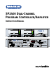
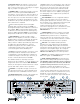
SP2400 Dual-Channel Program Controller/Amplifier Instruction Manual MASTER VOLUME ZONE A MASTER VOLUME ZONE B 3 0 3 6 9 15 30 55 INPUTS 3 0 3 6 9 15 30 55 INPUTS SP2400 MUSIC CONTROLLER A B OVERLOAD 1 2 3 4 1 2 3 4 OFF 115V 60Hz FUSE 115/T8A 220 WATTS 230V 50Hz FUSE 230/T4A 220 WATTS DIRECT PAGING MIC PROGRAM INPUTS L THE FOLLOWING ARE TRADEMARKS OR REGISTERED TRADEMARKS OF MACKIE DESIGNS INC "MACKIE.","MACKIE INDUSTRIAL", AND THE "RUNNING MAN" FIGURE.
CAUTION AVIS 8. Power Sources — Connect the SP2400 to a power supply only of the type described in these operation instructions or as marked on the rear panel. RISK OF ELECTRIC SHOCK DO NOT OPEN RISQUE DE CHOC ELECTRIQUE NE PAS OUVRIR 9. Power Cord Protection — Route power supply cords so that they are not likely to be walked upon or pinched by items placed upon or against them, paying particular attention to cords at plugs, convenience receptacles, and the point where they exit the SP2400.
2. INTRODUCTION The SP2400 is a microprocessor-based dualchannel music controller with two built-in power amplifiers designed for use in a variety of installations requiring high performance, flexible features, and ease of use, such as retail stores, restaurants, bars, and theme venues. It provides two outputs that can be used for either stereo operation or two-zone coverage. Four stereo line-level inputs are provided on the rear panel, along with a paging mic input and two local mic/line inputs.
FRONT PANEL FEATURES REAR PANEL FEATURES INPUTS select buttons are used to choose the program source for its respective zone. Only one source may be selected at a time. These are nonpriority inputs. However, Input 4 can become a Program Priority Input by setting the AMP ADDRESS switch #7 UP. In this mode, when a signal is present on Input 4, it automatically overrides whatever input source is selected for that zone. This is useful for jukeboxes or alternative paging configurations.
SP2400s together in a serial fashion. Any of the four program sources from any SP2400 can be used as the source for any of the zones in the system by assigning it to the expansion bus with the internal Bus Assign switches. This is a balanced bus for the four stereo input sources. In addition, the paging mic and paging control signal are also provided on the EXPANSION bus. MIC/LINE INPUT is provided to connect a local microphone in each zone.
3.
Jukebox Cassette or DAT Recorder Zone B Remote Control CD Player Digital Satellite Service +3 0 –3 –6 –9 – 15 – 30 – 55 Paging Mic To Telephone System Music-On-Hold Paging Mic Control Switch A B ALL INPUT 4 PRIORITY OFF/ON ZONE A 230/115V 50/60 Hz FUSE 115/T8A AMBIENT MIC OFF/ON UP 1 2 3 4 MASTER/SLAVE DOWN SP2400-1 SWITCH SETTINGS DIRECT 1 2 3 4 5 6 7 8 EXPANSION OUT 1 TO REDUCE THE RISK OF FIRE REPLACE WITH SAME TYPE FUSE AND RATING MIC/LINE INPUT B PHANTOM OUTPUT G – OFF ON A G
Jukebox Zone A Remote Control Cassette or DAT Recorder +3 0 –3 –6 –9 – 15 – 30 – 55 CD Player Digital Satellite Service AMBIENT MIC OFF/ON INPUT 4 PRIORITY OFF/ON ZONE A Paging Mic I 0 1 2 3 4 5 6 7 8 Zone A Remote Control OFF ON UP 1 2 3 4 MASTER/SLAVE DOWN SP2400-1 SWITCH SETTINGS 230/115V 50/60 Hz FUSE 115/T8A DIRECT 2 3 OFF ON + MIC/LINE INPUT B PHANTOM – A G B 1 2 3 G + – AMP ADDRESS 3 RS485 + – GAIN +40dB GAIN CONTROL LOW HIGH 2 3 4 1 2 3 4 2 1 OUTPUT PR
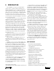
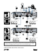
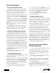
Note: This application provides independent source selection for each zone, or common input source selection for both zones (room combining). Both DX8 Selection Remote Controls are used to select Presets 1 and 2. For example, Preset 1 might route the CD Player and the Zone A microphone to Zone A, and the Cassette Player and the Zone B microphone to Zone B, to be used when the divider is in place between the two zones.
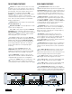
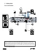
Application Diagrams A: Typical Stereo Application This diagram depicts a typical setup, using the SP2400 in a stereo application. A Digital Satellite Service (DSS) is connected to Input 1, which also serves as the music-on-hold for the telephone system. A CD player and cassette deck are connected to Inputs 2 and 3 for general purpose music playback. A jukebox is connected to Input 4, which is configured for priority playback via AMP ADDRESS switch #7.
in stereo. The answer to this question will also affect the location of the speakers in the room and the settings for the STEREO/MONO switches for the input sources. 3. How many program sources are going to be used? If the number of program sources is four or less, they can be centralized at one SP2400 and distributed via the Expansion Bus. If there are more than four program sources, they must be distributed among the SP2400s.
the amplifier output is configured for 8-ohm operation, connect the speaker output directly to an 8-ohm load. The amplifier will deliver up to 250 watts to each speaker. If the amplifier is configured for either 70V or 100V operation, connect the speaker output directly to the distributed system. No output transformer is required. Make sure that the taps on the speakers add up to 200 watts or less per amplifier for 70V or 100V systems.
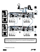
There are two 8-position DIP switches on the Input Board that allow you to assign a Program Input source to the balanced expansion bus. Each Program Input Source has four corresponding switches: Left (+), Left (–), Right (+), and Right (–). Typically, you would move all four switches either down (off) or up (assign to expansion bus). CAUTION: Never assign more than one program source to the same channel on the Expansion Bus. Assigning sources from more than one SP2400 onto the same bus may damage the unit.
EQ Bypass Jumper J6, located on each Filter Board, allows you to bypass the 3-band EQ for the four Program Inputs. configuration than the default settings. Refer to the following illustration for the locations of the jumpers. Note: Each amplifier board must be configured separately. On the Amplifier Boards Jumper pins 1 and 2 to bypass the EQ. Jumper pins 2 and 3 to engage the EQ (default).