
Owner`s manual


10
QUAD COMP/GATE
QUAD-COMP/GATE
11
Owner’s Manual
Owner’s Manual
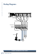
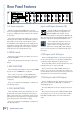
Rear Panel Features
1. AC Input receptacle
This is a standard 3-prong IEC power connector.
Connect the supplied detachable linecord to this power
receptacle, and plug the other end of the linecord into
an AC outlet.
The internal universal power supply can accept any
AC voltage from 100 VAC to 240 VAC. It will work virtu-
ally anywhere in the world, so that’s why we call it a
“Planet-Earth” power supply! The power supply is less
susceptible to voltage sags or spikes than conventional
supplies, providing greater electromagnetic isolation
and better protection against AC line noise.
2. POWER switch
Press the top edge of this rocker switch in to turn on
the Quad Comp/Gate.
Turn it off by pressing the bottom edge of the rocker
switch.
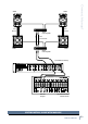
3. SIDE CHAIN SEND
These 1/4" TRS jacks output the channel signals after
the gate section, and before the compressor.
These can be connected to an external EQ or pro-
cessor, and then back to the RETURN [4] of the same
channel or a different channel for triggering of the
compressor.
They can accept balanced TRS plugs, or unbalanced
1/4" TS plugs, tip hot.
4. SIDE CHAIN RETURN
These 1/4" TRS jacks are used as inputs to the com-
pressor’s sidechain input. Any signals coming in here
will be used to trigger the compression of that channel.
(The signals are not going into the compressor’s audio
path, just its detector and leveling circuits.)
They can accept balanced TRS plugs, or unbalanced
1/4" TS plugs, tip hot.
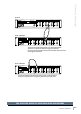
Inputs and Outputs (channels A-D)
The IN and OUT jacks will pass through
signals if the power is not applied to the
Quad Comp/Gate. For example, if your
mixer’s left main output is coming into the Quad Comp/
Gate channel-A input, the same signal will appear at the
channel-A output jack if the Quad Comp/Gate is off.
These inputs and outputs are line-level,
and you would normally connect them to
a mixer or line-level component in your
system. For example (OK, a bad example),
do not connect microphones or instruments directly to
the inputs.
5. TRS Inputs and 6. XLR inputs
These 1/4" TRS (tip-ring-sleeve) jacks are the inputs
for the channels. They can accept balanced TRS plugs,
or unbalanced 1/4" TS (tip-sleeve) plugs, tip hot.
The female XLR jacks are also the inputs for the chan-
nels (pin 2 hot, pin 3 cold, pin 1 shield).
For each channel, the XLR and TRS inputs are in
parallel, so you can choose either style as an input. You
can use unbalanced TS connections, but we recommend
using balanced connections wherever possible.
7. TRS Outputs and 8. XLR Outputs
These 1/4" TRS jacks are the outputs for the channels.
They can accept balanced TRS plugs, or unbalanced
1/4" TS plugs, tip hot.
The male XLR jacks are also the outputs for the chan-
nels.
For each channel, the balanced XLR and TRS outputs
are in parallel, so you can choose either style of output.
Both TRS and XLR outputs can be driven simultane-
ously.