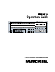
SDR 24 24/96 Operation Guide 96 SDR 24 TRACK/24 BIT DIGITAL AUDIO RECORDER ERROR 44.
SDR 24/96 CAUTION AVIS RISK OF ELECTRIC SHOCK DO NOT OPEN RISQUE DE CHOC ELECTRIQUE NE PAS OUVRIR CAUTION: TO REDUCE THE RISK OF ELECTRIC SHOCK DO NOT REMOVE COVER (OR BACK) NO USER-SERVICEABLE PARTS INSIDE REFER SERVICING TO QUALIFIED PERSONNEL ATTENTION: POUR EVITER LES RISQUES DE CHOC ELECTRIQUE, NE PAS ENLEVER LE COUVERCLE. AUCUN ENTRETIEN DE PIECES INTERIEURES PAR L’USAGER. CONFIER L’ENTRETIEN AU PERSONNEL QUALIFIE.
Introduction ----------------------------4 Save your Box! -------------------------------How To Use This Guide --------------------Conventions ---------------------------------About “Tape” --------------------------------Overview -------------------------------------- 4 4 5 5 6 Setup & Configuration----------------7 Required Equipment ------------------------ 7 Installation------------------------------------ 7 I/O Connections and Cables ------------------- 8 ----------------------------------------------
SDR 24/96 Introduction Save your Box! Uncle Jeff’s Bottom Ten Reasons to Save the Box: 10. You think boxes grow on trees? 9. It’s actually a time capsule, packed with a biological code that can’t be decrypted until 2043. 8. Its festive graphics will cheer up those other boxes forgotten in your attic. 7. Impress your friends: tape it up and pretend that you actually have two SDR24/96s. 6. If you throw it away, bad people will know you have a studio in your house. 5.
The SDR24/96 Operation Guide uses the following conventions to help you find information quickly: Text Conventions a) Text referring to the LCD display use medium weight (example: SETUP MENU) b) Text referring to hardware controls or connectors use heavy weight (example: STOP) Icons This icon identifies in-depth explanations of features and practical tips. Though not required reading, they do offer some choice tidbits of knowledge that will leave you wiser for the reading.
SDR 24/96 Overview By combining traditional multitrack tape recording features with the power and flexibility of non-linear editing, the Mackie Designs SDR24/96 takes multitrack recording to a level never before achieved by a product in its price range. In addition to the standard battery of traditional tape-based features, the SDR24/96: • Combines the familiarity of a multitrack tape machine with the security of non-destructive recording and non-degrading recording media.
This chapter explains how to set up and configure the SDR24/96 for use in your studio. Two application examples show how to interface the SDR24/96 with analog and digital recording consoles. Required Equipment Of course, there’s more to a studio than a recorder and some musicians. At a minimum, you’ll need the following to make the SDR24/96 feel at home: • A console with a minimum of 24 tape sends (buses or direct outputs) and returns (line inputs or monitor returns).
SDR 24/96 I/O Connections and Cables I/O connections are available in either analog or digital and can be used in any combination: Analog • Each 25-pin D-subminiature (DB25) connector provides eight balanced analog line-level inputs or outputs. These connectors are pin-for-pin compatible with the analog (not TDIF) DB25 connectors found on the TASCAM DTRS recorders (see Appendix D: Analog I/O Pinout).
be used to send or receive MIDI Time Code (MTC) and MIDI Machine Control (MMC) when connecting to equipment with transport controls and a position display. • ADAT SYNC OUT — This 9-pin D-subminature connector connects to the SYNC IN connector on an ADAT multitrack recorder when the SDR24/96 is providing the master sample clock. Use male-to-male 9-pin D-sub (DB9) cable.
SDR 24/96 The following is the recommended setup for establishing proper sample clock synchronization with the devices connected to the SDR24/96. ADAT Optical With the SDR24/96 as a master, set the receiving device(s) to derive sample clock from their ADAT optical ports if the ports are self-clocking. In this case, no word clock connection is necessary.
The SDR24/96 emulates the tape library tradition with Mackie Media M•90 and Mackie Media PROJECT drives. Both drives come complete with a plug-in tray for quick removal and a nifty storage case for shelving and transporting the drives. The SDR24/96 can record or play directly off the M•90 so you can change sessions as quickly as changing tape on a 24-track—no backup time required. PROJECT drives are for backup only and use removable 2.2GB ORB cartridges that fit in your pocket.
SDR 24/96 Hookups This section shows how the SDR24/96 is typically connected to both analog and digital consoles (using the Mackie Analog and Digital 8•Bus consoles as examples). These examples assume that the rest of your studio equipment (monitors, sound sources, outboard processing, etc.) is already connected, or that you know how to connect it.
SDR24/96 Settings 1. Set the Sample Clock (SETUP:Sync:SClk) to Internal. 2. Set the Sample Rate and Sample Size according to your preference. Console Settings Set the 24•8 console to the nominal +4 dBu operating level by setting the five Operating Level switches in the Sub Out and Tape Return sections to the ‘out’ position. This example describes the hookup for the D8B console equipped for analog I/O. Operation Guide 2. Connect three break-out cables to the SDR24/96 Outputs (top connectors).
SDR 24/96 Digital Hookup This example describes the hookup for the D8B console equipped for digital I/O (DIO•8 or OPT•8). Cables & Hardware (3) DIO•8 or OPT•8 cards for D8B (1) Apogee Clock I/O card for D8B (if D8B is the slave) (6) ADAT optical cables (1) 75Ω BNC word clock cable Hookup 1. Connect three ADAT optical cables from the SDR24/96 DIGITAL optical outputs to the optical inputs on the corresponding D8B I/O cards.
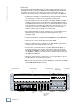
ADAT Optical Hookup with DIO•8 ANALOG OUT 9 - 16 ANALOG OUT 17 - 24 ANALOG IN 1 - 8 ANALOG IN 9 - 16 ANALOG IN 17 - 24 SDR POWER DIGITAL DIGITAL DIGITAL WORD CLOCK I/O IN 9 - 16 OUT IN 17 - 24 OUT IN IN MIDI SMPTE OUT IN 1- 8 USB IN FOOT SWITCH OUT 96 HIGH RESOLUTION NON-LINEAR RECORDER 24 TRACK/24 BIT DIGITAL AUDIO RECORDER MICRO/ REMOTE 24 CNTRL ADAT SYNC OUT OUT OUT ADAT SYNC IN X2 9-12 CAUTION WARNING: UTILISE UN FUSIBLE DE RECHANGE DE MÊME TYPE.
SDR 24/96 Remote 24/Micro Remote (Optional) Installing either remote is as simple as plugging in a telephone. Connect one end of the cable (supplied with the Remote) to the MICRO/REMOTE 24 CNTRL jack on SDR24/96 rear panel, and the other end to the TO HDR REMOTE JACK on the Remote 24, or to the TO SDR REMOTE JACK on the Micro Remote. It’s OK to plug or unplug either remote with the SDR24/96 powered on. Note: The Remotes duplicate nearly all of the front panel operating controls.
Operation Guide Configuration Before starting a Project, you will need to configure the SDR24/96 I/O options and synchronization parameters. These parameters determine where the input signal is coming from, where the sample clock is coming from, how fast the sample clock runs, and how many bits are recorded in every sample. Some options, like sample rate and bit depth, will become “standards” that you won’t need to change very often.
SDR 24/96 3. Select 1-8. The LCD display shows you the current setting for outputs 1-8, either Direct or Custom. Note: The front panel display’s backlight switches off after ten minutes of inactivity. You can revive it at any time by pressing either the Page Left [<] or Page Right [>] button, or any Select button below the display. TRK 1- 8 OUT: Direct Direct Custom Exit 4. Select Direct for direct track-to-output playback (i.e., Track 1 to Output 1, Track 2 to Output 2, etc.). 5.
The Sync Options menu (under SETUP) allows you to select the sample clock source, sample rate, time code source if time code chase is enabled, frame rate, and sample size. Sample clock source, time code source, LTC output, and MTC output are global settings, and are project independent. Sample rate, frame rate, and sample size are saved in the project file. Sample Clock SETUP MENU > The Sample Clock setting Record I/O Sync Transp (SETUP:Sync:SClk) determines the source of the SDR24/96 sample clock.
SDR 24/96 Frame Rate There are four standard time code frame FRAME RATE: 30 rates, each developed for a specific << >> OK application. In addition, two of the frame rates have variations called drop-frame, mostly used by broadcasters to correct timing issues caused by the 29.97 frame rate. Use Frame Rate (SETUP:Sync:FrRate) to set the time code frame rate to one of the following settings: 24, 25, 29.97, 29.97 Drop, 30, 30 Drop.
Operation Guide SDR24/96 Operation Now that you’ve finished installing and configuring the SDR24/96, you’re almost ready to start your first Project. We still want you to read this entire guide, but we already hear some of you shuffling and muttering. Okay, okay, okay... for the terminally impatient, read this chapter, then you can go out and play with your friends.
SDR 24/96 4. Press the Page Left button when finished, and then select New. New project created appears in the display to confirm that the project was successfully created. Opening a Project Once two or more projects have been created, you can switch projects easily with the Open Project command. To open a Project: 1. Press Project. In the Project Files Menu, select Open. PROJECT PROJECT FILES MENU > New Open Save SaveAs 2.
A project can contain any number of project files. Since the audio referenced in one project file can be used in any project file, you can create multiple versions of the same song without affecting the original recording. For example, you can create dance and extended play mixes from a CD mix. Or, you can build an entirely new song and borrow parts from other project files. To save a current Project As: 1. Press Project. In the Project Files Menu, select SaveAs. PROJECT 2.
SDR 24/96 Copying a Project The importance of backing up your files cannot be emphasized enough. Do it often. Hopefully, you’ll never need to use a backup copy of your project, but you’ll thank yourself a hundred times over if you ever need it. To copy a Project: 1. Press Project. Press the Page Right button, and in the Project Files Menu, select Copy. PROJECT PROJECT FILES MENU > New Open Save SaveAs < PROJECT FILES MENU Delete Copy Rename Purge 2.
You can give a project a new name at any time. The project cannot be open when you rename it. To rename a Project: 1. Press Project. Press the Page Right button, and in the Project Files Menu, select Rename. PROJECT PROJECT FILES MENU > New Open Save SaveAs < PROJECT FILES MENU Delete Copy Rename Purge 2.
SDR 24/96 To purge a Project: 1. Press Project. Press the Page Right button, and in the Project Files Menu, select Purge. PROJECT 2. The Purge current project? screen appears. Select OK to delete files not referenced in the project file, or Cancel to exit. PROJECT FILES MENU > New Open Save SaveAs < PROJECT FILES MENU Delete Copy Rename Purge Purge current project? OK Cancel 3. The PURGE: clear history? PURGE: clear history? screen appears.
When the transport is already stopped, pressing and holding the STOP button for one second puts the transport into scrub mode. The STOP and PLAY LEDs light simultaneously and Entering scrub mode appears in the display. Use the REWIND and FAST FWD buttons to scrub the transport forward and backward. Press STOP or PLAY to return to normal mode. Play PLAY puts the SDR24/96 into play from any state (as if you didn’t know).
SDR 24/96 3. Select one of the four Locates (Loc1, Loc2, Loc3, Loc4). The current locate time appears in the display. 4. Select Zero to reset the Locate point to zero. LOC1: 00:12:34:56 > Zero OK Cancel < LOC1: 00:12:34:56 << >> Inc Dec 5. Press Page Right to change the locate time. A blinking cursor appears over the first numeral of the locate time. Use the increment (Inc) and decrement (Dec) buttons to change the highlighted numeral. Use the >> button to move to the next numeral. 6.
4. Select Zero to reset the transport offset time to zero. < TRANSPORT OPTIONS > CurLoc TrOf RelOf RelMd TRANSOF: 00:01:00:00 > Zero OK Cancel < TRANSOF: 00:02:00:00 5. Press Page Right to change << >> Inc Dec the transport offset time. A blinking cursor appears over the first numeral of the transport offset time. Use the increment (Inc) and decrement (Dec) buttons to change the highlighted numeral. Use the >> button to move to the next numeral. 6.
SDR 24/96 To turn on the relative mode: 1. Press SETUP to enter the SETUP MENU. SETUP SETUP MENU > Record I/O Sync Transp 2. Select Transp. to enter the TRANSPORT OPTIONS menu. 3. Press the Page Right button and select RelMd. Use the << / >> buttons to select On or Off, then select OK to change the relative mode.
Operation Guide To store numbered Locate points: Locate points can be stored either on the fly or when stopped. 1. Press STORE. The Store LED lights. E STORE 2. STORE LOCATOR appears in STORE LOCATOR: the display. Select one of the Loc1 Loc2 Loc3 Loc4 four Locate points in the display (Loc1, Loc2, Loc3, Loc4) when the transport is at the desired location. The Store LED goes out, indicating that the Locate point has been stored.
SDR 24/96 To record: 1. Arm one or more tracks. PLAY RECORD 2. Press RECORD and PLAY at the same time. Record can be activated during Stop or Play. If One Button Record is enabled, Record can be activated during play just by pressing the RECORD button. 3. Press any transport button other than RECORD to stop recording. The Record LED glows when the SDR24/96 is recording and blinks when RECORD is engaged with no tracks armed (master record standby mode).
There are a number of options available to make your recording session easier. Safe Mode Safe mode (SETUP:Record:Safe) disarms all tracks and disables the Record Ready and master Record buttons. Use safe mode to prevent anyone from inadvertently activating record mode and ruining your perfect song.
SDR 24/96 Locator Mode The locator mode setting (SETUP:Record:Page Right:LocMd) determines how looping and auto punch work. LOCMD: Loop1-2/Punch3-4 << >> OK ♦ With Loop1-2/Punch3-4 selected, Locates 1 and 2 double as start and end points for looped playback (see “Loop” on page 31 for more info), and Locates 3 and 4 serve as punch in and punch out points when Auto Punch is enabled (see “Auto Punch” on page 37 for more info).
Monitoring The Monitor Mode buttons determine what you hear from the SDR24/96 Tape Outputs. The SDR24/96 offers several familiar monitoring modes to facilitate rehearsal, tracking, and overdubbing. All Input All Input is used for rehearsal and level setting. When All Input is on, both armed and unarmed tracks monitor their inputs, and the Auto Input setting has no effect.
SDR 24/96 Metering and Setting Record Levels A professional analog recorder has meters that indicate 0 VU at a +4 dBu nominal signal level. Generally you can record peaks 10 to 15 dB above that before distortion becomes objectionable. This 10-15 dB range above the nominal level is called “headroom.” On digital recorder meters, zero represents the full-scale digital signal level, 0 dBFS for short. 0 dBFS is the hottest signal that a digital device can handle, with no headroom to spare.
Remember, audio levels must NEVER reach 0 dBFS... never, ever, ever. Digital clipping is an extremely nasty sound that could only pass for music if you like what those crazy kids listen to over and over at all hours of the night including weekdays. Auto Punch Auto Punch allows you to automatically punch in and out between two predefined points. This feature is very convenient when you need to nail a really tight punch or need two hands to play your instrument.
SDR 24/96 Use the increment (Inc) and decrement (Dec) buttons to change the highlighted numeral. Use the >> button to move to the next numeral. 6. Press the Page Left the new locate time. < LOC1: 00:12:34:56 << >> Inc Dec button when finished, and then select OK to save 7. Repeat steps 1-6 for Loc4. To perform Autopunch recording: 1.
Using a footswitch with the SDR24/96 gives you hands-free access to several of the most-used SDR24/96 functions. The footswitch is extremely handy when you want to use your hands for other tasks, like playing your instrument, working the console, or eating pizza. Punching in and out is probably the most common use of the footswitch, but it can stop and play as well. Punch punches-in just like pressing PLAY + RECORD and punches-out like pressing PLAY.
SDR 24/96 Editing Delete Last Pressing the DELETE LAST button removes the last record pass and automatically deletes the recorded audio, but only if the record pass is the last entry in the history list. If any other action is performed after the record pass that is recorded in the history list, pressing the DELETE LAST button results in the message Nothing to delete in the display. If the last record pass consisted of multiple punches, all of the recorded audio will be deleted, not just the final punch.
Cut This operation cuts the audio in the selected region on the selected tracks and puts it on the clipboard. EDIT MENU > 1. Press EDIT, select the tracks Delete Cut Copy Paste you want to cut (Record Ready), then select Cut. 2. You are asked whether to Splice after cut? Splice after cut? Yes No Cancel Operation Guide If you choose to delete followed by splicing (Yes): ♦ The audio in the selected area is deleted. ♦ The audio on either side of the deleted area is joined together.
SDR 24/96 ♦ ♦ ♦ ♦ the clipboard are not copied. If there are less tracks on the clipboard than selected tracks, the remaining selected tracks remain unchanged. The audio before and after the pasted area remains at its position. Audio regions pasted from the clipboard replace any existing audio on the selected tracks. Silence gaps pasted from the clipboard leave the existing audio unchanged. The clipboard content is unchanged. The paste action is added to the history list, and can be undone.
Undo This operation allows you to undo the previous action. If it was a record pass, you are asked whether or not to keep the audio. You can continue to undo EDIT T actions as you back down the history list. 1. Press EDIT, Page Right, and < EDIT MENU select Undo. Place Undo Redo 2. You are asked to confirm the undo operation. Select OK or Cancel. UNDO: Record pass 3. If it was a record pass, you are Proceed? OK Cancel asked if you want to keep the audio.
SDR 24/96 Undo, Redo, and Delete Last ♦ ♦ ♦ ♦ ♦ ♦ ♦ The history list contains all edit operations and recording passes in chronological order. The undo command moves up one entry on the history list; the redo command moves down one entry. Performing an edit operation or record pass permanently removes the undone actions from the history list. When a recording pass is to be undone, you are asked whether or not to keep the audio.
The Defrag option (SETUP:Page Right:Disk:Defrag) allows you to defragment a drive. As files are written, edited, and deleted on a disk, the files can become fragmented. The SDR24/96 still keeps track of the data, but it can slow down access to the files. Defragmenting a drive puts all the files back together in contiguous streams of data. As a precaution, we recommend backing up the data on the hard drive before running the defrag operation. To defragment a drive: 1. Press SETUP to enter the SETUP MENU.
SDR 24/96 Connect a USB cable between the USB port on the SDR24/96 and the USB port on your computer. Support for USB mass storage mode varies depending on the Operating System you are running on your computer. Here is an overview of USB mass storage support in various operating systems: ♦ Windows NT 4.0 has no USB support at all. ♦ Windows 95 and 98 have no USB mass storage support. Windows 98SE supports USB, but not USB mass storage.
The Date option (SETUP:Page Right:System:Page Right:Date) allows you to enter the current date. This is used to timestamp new and updated files. To reset the date: 1. Press SETUP to enter the SETUP MENU. 2. Press Page Right, select System, Page Right, and then select Date. DATE: 02/02/02 m/d/y > OK Cancel 3. Press Page Right to change < DATE: 02/02/02 m/d/y the date. A blinking cursor << >> Inc Dec appears over the first numeral of the date.
SDR 24/96 Appendix A: Troubleshooting and Service If you think your SDR24/96 has a problem, please do everything you can to confirm it before calling for service, including reading through the following Troubleshooting section. Doing so might save you from the deprivation of your Mackie Digital Audio Recorder and the associated suffering.
Service for the SDR24/96 Digital Audio Recorders purchased in the USA is available only from one of our authorized domestic service stations. It is also available at the factory, located in sunny Woodinville, Washington. (Service for Mackie products living outside the United States can be obtained through local dealers or distributors.) If your SDR24/96 needs service, and it lives in the United States, follow these instructions: 1. Review the preceding troubleshooting suggestions. Please. 2.
SDR 24/96 Appendix B: Technical Info SDR24/96 Specifications Electronic Frequency Response (Digital, 48 kHz sampling rate): Harmonic Distortion: Dynamic Range: Adjacent Channel Crosstalk (+10 dBu at 1 kHz): 20 Hz to 20 kHz (+ 0 dB, – 0.5 dB) 0.005% @ 1 kHz sine wave at –1 dBFS with 20 kHz brick-wall low-pass filter 108 dB digital (A-Weighted) –90 dB Digital Quantization: Sample Rates: 16-bit and 24-bit, selectable 44.1 kHz, 48 kHz, 88.
From time to time, Mackie may release updated versions of the SDR24/96 operating system on our website at www.mackie.com. The file can be downloaded easily from the SDR24/96 section of the site. To install new software: 1. Place the SDR24/96 into USB mass storage mode (SETUP:Page Right:System:USBMS). See “USB mass storage” on page 45 for more info. 2. Connect a USB cable between the SDR24/96 and your computer. 3.
SDR 24/96 Appendix E: Compatible Cables Analog and Digital Multitrack Cables The following companies supply analog and digital multitrack cables for use with the SDR24/96 Input and Output connectors: Horizon Music, Inc. P.O. Box 1988, Cape Girardeau MO 63702-1988 Tel: (800) 255-9822; Fax: (800) 455-3460 http://www.horizonmusic.
In addition to the companies listed above, the following companies supply individual 110Ω AES/EBU and/or 75Ω word clock and video cables: Apogee Electronics Corporation 3145 Donald Douglas Loop South Santa Monica, CA 90405-3210 Tel: (310) 915-1000; Fax: (310) 391-6262 http://www.apogeedigital.com Canare 531 5th Street, Unit A, San Fernando, CA 91340 Tel: (818) 365-2446; Fax: (818) 365-0479 http://www.canare.com Operation Guide Other Cables Whirlwind 99 Ling Rd.
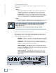
SDR 24/96 2 POWER 1 4 100 - 240V 250mA 50/60Hz POWER 3 5 USB 7 8 13 15 DIGITAL 14 16 TRACK STORE LOCATE 18 DELETE LAST 17 LOOP PROJECT 19 X2 1-4 OUT IN X2 5-8 OUT 9 - 16 1- 8 IN DIGITAL DIGITAL IN X2 9-12 17 - 24 OUT IN EDIT 20 21 AUTO INPUT ALL INPUT IN 24 48k SERIAL NUMBER OUT HOURS MINUTES SECONDS HIGH RESOLUTION NON-LINEAR RECORDER STOP FRAMES SELECT MICRO/ REMOTE 24 CNTRL EXT CLOCK RECORD SERIAL 9-PIN ADAT SYNC IN ADAT SYNC OUT HIGH RESOLUTION
________________________________________________________________________________________________ ________________________________________________________________________________________________ ________________________________________________________________________________________________ ________________________________________________________________________________________________ ________________________________________________________________________________________________ ___________________________
16220 Wood-Red Rd. NE • Woodinville, WA 98072 • USA US & Canada: 800/898-3211 Europe, Asia, Central & South America: 425/487-4333 Middle East & Africa: 31-20-654-4000 Fax: 425/487-4337 • www.mackie.com E-mail: sales@mackie.