4-CH & 8-CH Digital Video Recorder Quick Installation Guide Version: 1.
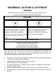
WARRINGS, CAUTION & COPYRIGHT WARINGS Reduce the risk of fire or electric shock. And do not expose this product to rain. Do not insert any metallic object through ventilation grills.
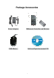
Package Accessories Power Adaptor IR Remote Controller and Batteries USB Mouse Software/Operation manual CD 1
1.
3
4
5
6
7
2.
3.
3.
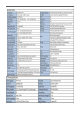
4. Economy 8 Channel Front Panel Function Interface 1 ENTER 8 Search 15 SEQ 2 Direction Control 9 Copy 16 Mode 3 Recording 10 MENU /ESC 17 USB Backup 4 Fast Forward 11 +/LIVE Display 18 Power LED 5 Play / Pause 12 -/QUAD Playback 19 Network LED 6 Stop 13 Page 20 IR Receiver 7 Fast Rewind 14 Call/PTZ : NOTE: BACKUP function also can be copy function to copy DVR setting.
5.
6.
7. Function Control Illustration The Chapter will explain How to use the function of panel button. illustration item as below: Please follow the MENU/ESC Button: In the MONITOR mode, press the button to change the viewing mode to the Menu. The “SETTING” mode offers 10 kinds of sub-mode. Please select the sub-mode through the “Control” button. The default selection is “Log In/Out”. In the SETTING mode, the button function will change to ESC function.
In PTZ control mode, press these buttons to zoom out the camera. – In MONITOR or PLAYBACK mode, press these buttons to less the volume. In PTZ control mode, press these buttons to zoom in the camera. Rec: The DVR support multiple working. You can view, record, playback and remote control at the same time. The DVR will automaticity record the image on DVR boot finish. Press this button to force manual recording. To stop manual recording, press it again.
MOUSE RIGHT KEY: You can be click the mouse “right-click” used as MENU/ESC key.
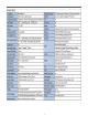
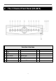
8. The 4 CH Rear Panel (KA-6614) Hardware Interface 1 CAM Input (1 CH) 9 2 CAM Input (3 CH) 10 Monitor Out 3 Audio Output 11 Audio input (IN2) 4 Audio input (IN1) 12 RJ45 Ethernet Connecter 5 VGA Connecter 6 USB Mouse 7 DC 12 V Power Adapter 8 CAM Input (2 CH) NOTE: : The mouse must set up before the DVR power on.
9. The 4 CH Rear Panel (KA-6714) Hardware Interface 1 CAM Input (1~4 CH) 9 2 Audio Output 10 3.5 mm IR Receive 3 Audio input 11 DC 12 V Power Adapter 4 VGA Connecter 5 Power Switch ON/OFF 6 USB Mouse 7 Moniter (MAIN OUT) 8 RJ45 Ethernet Connecter : NOTE: The mouse must set up before the DVR power on.
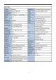
6. The 8 CH Rear Panel (KA-6618) Hardware Interface 1 CAM Input (1 CH~8CH) 9 2 Audio Output 10 IR extend 3 Audio input (IN1~IN2) 11 DC 12 V Power Adapter 4 VGA Connecter 5 Power switch 6 USB Mouse 7 Monitor Out 8 RJ45 Ethernet Connecter NOTE: : The mouse must set up before the DVR power on.
10. Economy 8 CH Rear Panel Hardware Interface 1 CAM Input (1~8 CH) 9 2 Audio Output 10 3.
11. The 4 CH Rear Panel (KA-2814) Hardware Interface 1 CAM Input (1 ~4CH) 9 2 Monitor Out 3 Audio input (IN1) (IN2) 4 RJ45 Ethernet Connecter 5 VGA Connecter 6 USB Mouse 7 DC 12 V Power Adapter 8 Audio Output NOTE: : The mouse must set up before the DVR power on.
12. The 8 CH Rear Panel (KA-2818) Hardware Interface 1 CAM Input (1 ~8CH) 9 2 Monitor Out 10 VGA (Reserve) 3 Audio input (IN1) (IN2) 11 Power Switch ON/OFF 4 RJ45 Ethernet Connecter 12 USB Connecter 5 RS485 Connecter and Alarm 4 in 2 out 6 3.5mm IR Receive 7 DC 12 V Power Adapter 8 USB Mouse NOTE: : The mouse must set up before the DVR power on.
13. Image Input and Output The DVR provides 4CH video input and output. Video Input Cameras connect to BNC connectors. Monitor Output Connect TV monitors to the BNC connector for main monitor display. VGA Connect VGA monitor to the VGA connector for display. NTSC/PAL Switch Select NTSC or PAL according to the local TV system.(adjust switch inside the main board) NOTE: : You must select the DVR system before DVR booting. system, please power off the DVR first.
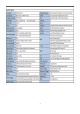
14. Monitor Display Illustration MONTOR Mode 12 1 10 9 11 8 3 7 6 5 2 4 MONITOR Mode Display illustration Number Item Camera explanation 1 Camera name Image name of display 2 Date / Time Show the real time date and time information. Scrolling Banner It will show the status of motion, alarm, V. loss, HDD and DVR state.
PLAYBACK Mode 1 10 11 9 8 3 7 6 5 2 4 PLAYBACK Mode Display illustration Number Item Explanation 1 Camera name The playback recording image name 2 Date / Time Show the real time date and time information. Scrolling Banner It will show the status of motion, alarm, V. loss, HDD and DVR state.
MENU SETTING Mode 3 2 4 1 5 9 6 8 7 MENU SETTING Mode Display illustration Number Item Explanation 1 Log In/Out Login the DVR through the account 2 System info Show the DVR system information 3 Video Adjustment Adjust the camera setting 4 VGA Display Adjust the VGA setting 5 Backup Use the backup function 6 Setup Enter the SETTING Mode 7 Firmware Update the DVR firmware through USB Flash 8 Shutdown Power off the DVR 9 Exit Leave the MENU SETTING mode 26
SETUP SETTING Mode 7 2 3 1 4 5 8 9 12 10 11 6 SETUP SETTING Mode Display illustration Number Item Explanation 1 Camera Group Set up the DVR resolution, PTZ and Watermark 2 Camera Set up the camera info, motion, quality and fps 3 Alarm Set up the extra alarm function 4 SEQ Display Set up the SEQ setting 5 Schedule Rec Set up the alarm, motion or always recording 6 HDD Set up the HDD recording and figure 7 Password Manage the DVR’s account 8 System Set up the DVR time and
SEARCH Mode 2 1 3 4 6 5 SEARCH Mode Display illustration Number Item Explanation 1 Time Search Select the date and time to playback recording image 2 Event Search Select the event to playback recording image 3 Smart Search Choice the motion area to playback the recording image 4 Archive Search Search the backup device recording image 5 POS Search Define the keyword of pos recording data for playback 6 Exit Leave the SEARCH mode 28
15. Mouse Control Illustration When installing and using the mouse interface, the main menu interface will be needed to operate with mouse.
16. Audio Input and Output Connect audio IN or OUT devices through RCA interface. Audio Input These RCA connectors accept audio signals supplied from external devices. Audio Output These connectors supply audio signals to external devices. from AUDIO OUT during playback. Recorded audio will be supplied NOTE: : The Audio function cannot guarantee power issue. Please notice whether the microphone spec can use or not. 17. Other Interface The DVR have some application function for User.
Alarm IN and OUT: The DVR can work TTL/COMS alarm signal for the LOW & HIGH of potential or the N.O & N.C state. ALARM INPUT: : Support 4 ch alarm input. The extra device connects one for the alarm input, the other for GND. Connect these connectors to external devices such as sensors or door switches. ALARM OUTPUT: : Support 2 alarm output. Connect these connectors to 1 Normally Closed (NC) alarm outputs and 1 Normally Open (NO) alarm outputs.
18. DVR Quick Setup Guide: This quick start guide will help you become familiar with our DVR in a very short time. How to play basic PLAYBACK function: In the search menu, select “Search by Time” Then set Year, Month, Date, Hour, Minute, execute “PLAY”. How to quick setup RECORD function: Select “SETUP” of the main menu. Select “Camera” Set each channel of “Title, Record Quality, Record Fps.” Confirm this setting and save.
How to setting MOTION function: Select “SETUP” of the main menu. Select “Camera” Select Detection to enter the “Settings” Into Motion mode. In the Motion mode, press “+/-” button to enlarge or reduce the area.
Press the button to set/reset the whole video area Press the button to test the motion detection of the camera Choose the area where you want to displace, Click “ESC” to save this config setup 34
19. Network: In SETUP SETTING Mode, press Direct Control button to change the highlighted option to Network, and then press ENTER to call up Network Setup as shown. The Network Setup allows the administrator to setup all Ethernet network related parameters. Please check with your network administrator to set these parameters correctly. The general operations are as below: Direct Control Press these buttons to select the items.
Net Mask – Net Mask for the IP address. Gateway – Gateway IP address for the system. DNS – DNS (Domain Name Server) IP address for the system. Username – PPPoE username for the system if PPPoE is used. Password – PPPoE password for the system if PPPoE is used. DDNS Type – Dynamic, Static, Custom DDNS (Dynamic Domain Name Server) type, etc. Please contact your local DDNS Service Provider to get the DDNS URL, username, and password. Press +/- buttons to change this item.
2. If you have the account in the DynDns.org, you can skip the illustration to no.9. However, if you don’t have the account, please click the “Create Account” button through the left-mouse. 3. You will see the table of account, and then input the needful information such as: “User Information” and “Terms of Service”. You can input other information by yourself. 1 2 4. After input finish, please click the “Create Account” button.
6. Click the red square to finish the creative account. 7. You can login to DynDns.org, please input the username and password on main webpage. And click the “Service” button to set up the DDNS function. 8. Please select the “Dynamic DNS” button. 9. Click the “Get Started” button to add the new Hostname.
10. Set up the “Hostname” and “IP Address” by yourself. You can enter your favor domain name to “Hostname”, and input correct “IP address” to IP Address. Finally, click the “Add Host” to finish the setting. 11. The DDNS information will display on the webpage in the end. 12. Please try to connect to the DVR through domain name. 13. If you cannot connect the DVR through domain name, you can test the DDNS service on your PC. 14. Please open the “command mode” from “Start Menu”. 15.
16. If the command mode display the figure information. Your DDNS is correct. 17. If the command mode display the “timed out” information. Your DDNS is wrong. E-Mail Setup: In Network Setup, press ENTER to call up E-mail Setup as shown when the highlighted option is E-mail. The E-mail Setup allows the administrator to set e-mail related parameters. When an event occurs and E-mail is enabled for the corresponding action, an e-mail will be sent based on the parameters set here.
MENU/ESC Press this button to escape from this screen, and return to Network Setup display. If the Save dialog is shown, press ENTER to exit and save, MENU/ESC to exit without saving. Following is a brief description for each item and its specific operations: SMTP Server – SMTP mail server name. SMTP Port – the SMTP port for e-mail transmission. The default value is 25. Authentication – whether the SMTP mail server requires authentication. Press ENTER or +/- to check/uncheck this item.
FTP Setup: In Network Setup, press ENTER to call up FTP Setup The FTP Setup allows the administrator to set FTP related parameters. When an event occurs and FTP is enabled for the action, the recorded video/audio for that event will be sent to the FTP server based on the parameters set here. The general operations are as below: Direct Control Press these buttons to select the items. MENU/ESC Press this button to escape from this screen, and return to Network Setup display.
empty, the filenames will be “cam..”; if not, the filenames will be “Prefix-cam..”. For example, if the prefix is “DVR01”, then the filenames will be “DVR01-cam..”. Advanced Network Setup: In Network Setup, press ENTER to call up Advanced Network Setup as shown when the highlighted option is Advancing function. The Advanced Network Setup allows the administrator to set advanced network parameters. If the user is not familiar with network administration, please DO NOT modify the items in this dialog.
WAP Picture Quality – the WAP picture quality if WAP access is supported for the DVR. Press +/- buttons to change the value. IP Filter #1-4 – the IP filters #1-4 for remote access. Only those PCs with IP addresses matching one of the IP filters can access the DVR remotely. NOTE: : If the Control Port or Data Port is not available or accessible during remote access, the system will reset the ports to their default values, i.e. 67/68.
20. USB / DVD Playback After the backup image finish, the USB flash/DVD will include the “SelfPlayer” software and backup recording image file. You can direct to view the backup image through PC/Laptop. You need to plug the USB flash/DVD into PC, and then open the disk of USB flash/DVD. Click "SelfPlayer.exe" to execute the DVR software Click the “File” area then click the “Open" button to select the backup recording file. Open the USB/DVD disk located driver letter. (Example F:).
21. Remote view You can remote view the image of DVR through internet on the world. Just input the IP address or domain name on “I.E Browser”. The remote function would support viewing image, playback image and recording image. System Requirements of Remote PC It is recommended to access the digital video/audio recorder using a PC that meets the following system requirements. PC IBM PC/AT compatible with Intel® Pentium® 4, 1.7 GHz or above CPU.
DirectX® End-User Runtime 9.0 It has been installed in your PC successfully. download of it. If not, please logon to web page to get the free NOTE: : Web Page: http://www.microsoft.com Windows XP KB319740 Package It has been installed in your PC successfully if the PC is running Windows XP SP2. If not, please logon to web page to get the free download of it, or install it from the corresponding directory in the CD. (This package is a bug fix for Windows XP SP2.) NOTE: : Web Page: http://www.microsoft.
You need to change the security setting of I.E Browser. Please follow the step by step illustration as below: Open the I.E Browser select the “Tools” “Internet Options”. Select the “Security” bookmarker Custom Level Security Settings NOTE: : The domain name or IP address of the digital video/audio recorder has been set as trusted web site in your PC, and the (https:) server verification for trusted web site is unchecked. If not, please go to Tools->Options->Security in your I.E.
Enabled or Prompt the selection of Download unsigned ActiveX controls, and then click the “OK” button to leave setting. Open the I.E Browser and input the IP address or domain name of DVR. Press the “connect” button. The I.E Browser will pop-up the window, please click the “Install” button to set up the software of ActiveX. After install finish, the Internet Explorer pop-up the window again. Please input the user name and password to enter the network viewing mode. NOTE: : The default username is “abc”.
After the above-mentioned items have been done correctly, restart your web browser and enter the domain name or IP address (EX. http://192.168.1.100 if HTTP port is 80, or http://192.168.1.100:800 if HTTP port is 800) of the digital video/audio recorder in the Location/Address field of the web browser. The plug-in software in the system will be downloaded and run automatically in the web browser. NOTE: : Please note that up to 8 users can logon this DVR simultaneously.
In video window, right-click the mouse button to call up Camera/Playback/Print Dialog. (Left) click on Playback or Camera number to change the window to the corresponding camera and live/playback mode. The user may also click on the “Print” button to print the video to the printer, or “Snapshot” the video. 22. Support GPS / POS The DVR can support all GPS / POS on the market. Please reference to the details manual in the CD. 23. Support Hardware List There are many HDD spec.
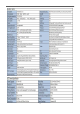
Appendix C: 24. Support USB Flash and DVD List Support USB Flash and DVD List There are many USB Flash and DVD spec. Please suggest the list to buy the applicable hardware that combine with the DVR. Type Format USB-Storage Enclosures 5.25” Macpower’s Alumni Prefect USB 2.0 - PF-U2MS.
25. PDA / Mobile Phone Remote Access The digital video/audio recorder can also be remotely accessed by using a web browser installed on a PDA or mobile phone. (1) Supports xHTML and MJPEG file format (2) The screen resolution will at 240x320 or above. (3) Support i-phone / Firefox / Symbian 6.0 / Apple / Linux / Windows Mobile Please enter the domain name or IP address of the digital video/audio recorder in the Location/Address field of the web browser, and the remote login display will be shown.
26. Firefox browser Remote Access Users want to use Firefox browser to access the system, make sure that the following: 1. Execute Firefox. 2. 3. 4. 5. Login “http://ietab.mozdev.org” web, Select Tools>IE Tab option. Select Sites Filter. Select “Sites list here will always render using embedded IE”,and add the s http://xxx.xxx.xxx.xxx/ie.htm sites to the local pc. 6. Enter DVR path http://xxx.xxx.xxx.xxx/ie.