6 INPUTS STANDALONE H264 DIGITAL VIDEO RECORDER ART. 49136 Please read this manual thoroughly before use and keep it for future reference. Via Don Arrigoni, 5 24020 Rovetta S. Lorenzo (Bergamo) http://www.comelit.it – E mail: export.department@comelit.
WARNING RISK OF ELECTRIC SHOCK DO NOT OPEN WARNING: TO REDUCE THE RISK OF ELECTRIC SHOCK, DO NOT REMOVE COVER (OR BACK). NO USER-SERVICEABLE PARTS INSIDE. REFER SERVICING TO QUALIFIED SERVICE PERSONNEL. The lightning flash with arrowhead symbol, within an equilateral triangle, is intended to alert the user to the presence of uninsulated "dangerous voltage" within the product’s enclosure that may be of sufficient magnitude to constitute a risk of electric shock.
Important Safeguards 1. Read Instructions All the safety and operating instructions should be read before the appliance is operated. 2. Retain Instructions The safety and operating instructions should be retained for future reference. 3. Cleaning Unplug this equipment from the wall outlet before cleaning it. Do not use liquid aerosol cleaners. Use a damp soft cloth for cleaning. 4.
Table of Contents 1. Product Overview················································································ 6 1.1 Features·························································································· 6 2. Panels And Remote Controller····························································· 7 2.1 Front Panel······················································································ 7 2.
6.10.2 Advanced Network Setup························································ 52 7. PTZ Control························································································· 53 8. Search/Playback/Archive (Administrator/Supervisor) ························· 54 8.1 Search By Time··············································································· 55 8.2 Search By Event / Log Display·························································· 56 8.
1. Product Overview The H264 digital video/audio recorders are designed for use within a surveillance system and are a combination of a hard disk recorder, a video multiplexer, and a web server. To achieve the highest inter-connectivity and inter-operability, this series of digital video/audio recorders are all based on industry-leading front-end to back-end surveillance infrastructure.
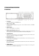
2. Panels and Remote Controller 2.1 Front Panel 1. Front Door Conceal Hard Disk Tray (for IDE HDD only). 2. USB connector (USB) Connect to USB 2.0 compatible storage device, such as USB 2.0 disk drive, DVD+RW, card reader, etc. 3. DVR ID Switch Used to set the DVR ID (1-4) of this unit. 4. Alpha-numeric Buttons (1-9, 0, *, #) Press these buttons for camera selection in most circumstances. These buttons can also be used to enter text and number in the way similar to most of the mobile phones. 5.
9. CALL Button Press this button to switch to or return from full screen display of the focus camera in main screen display. In some dialogs, this button is used as a miscellaneous function key. 10. SEQ Button Press this button to switch to or return from SEQ display mode in main screen display. In some dialogs, this button is used as a miscellaneous function key. 11. MODE Button Press this button to toggle between live mode and playback mode in main screen display.
21. Fast Backward Button ( ) Press this button for fast backward playback. 22. Play/Pause Button ( ) Press this button to play the recorded images or pause the playback. 23. Stop Button ( ) Press this button to stop the playback. 24. Single Step Button ( ) Press this button to play the recorded images frame by frame. 25. Fast Forward Button ( ) Press this button for fast forward playback. / / ) 26. (Vol/Zoom) +/- Buttons ( Press these buttons to change the volume in most circumstances.
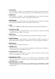
2.2 Back Panel 1. Video Input Connectors (1-16) Connect system cameras to these BNC connectors. The corresponding 75Ω termination (see # 5)must be made unless the video output terminal is connected. 2. Video Output Connectors (1-16) Connect these BNC connectors for looping the corresponding camera video inputs. 3. Stereo Audio Input Connectors (AUDIO IN 1-4) These RCA connectors accept 2 stereo line-in audio signals supplied from external devices such as microphone amplifiers. 4.
. RS-422/485 Selector Switch Used to select RS-422/485 4-line or 2-line. 12. RS-422/485 Connector Connect this connector to RS-422/485 compatible PTZ camera(s). Please set the Selector Switch correctly. Please refer to the manuals that come with the RS-422/485 compatible devices for the correct settings. 13. Alarm Input Connectors (ALARM IN 1-16) Connect these connectors to external devices such as sensors or door switches. 14.
2.3 Remote Controller The remote controller is an accessory to ease the user’s operations. You can do all the operations by the remote controller instead of the buttons on the front panel. The effective distance is about 10 meters without any obstacle. The Buttons Each of these buttons corresponds to one of those buttons on the front panel. Please refer to the descriptions in Section 2.1. 3. Installations The installations described below should be made by qualified service personnel or system installers.
Cameras Connect the camera video input connectors to the video outputs from system cameras or other composite video sources via coaxial cables. Main monitor Connect the main monitor output connector (BNC) to a surveillance CCTV monitor. The CCTV monitor displays selected live or recorded cameras in any available split window format. Hard disk drive(s) Make sure to install at least one hard disk drive inside the hard disk tray.
Alarm outputs Connect the alarm outputs 1-2 to NC type of alarm signals, alarm outputs 3-4 to NO type of alarm signals. Ethernet Connect the Ethernet connector to a standard twisted-pair Ethernet cable for remote access via LAN or internet. Please make sure to setup the related configurations as described in Section 6.10 Network Setup. USB 2.0 disk drives, DVD+RW, card reader, etc. If the user wants to use USB2.
N/C N/C GND RxD+ RxDTxD+ TxDGND Set this unit to 2-line For PTZ cameras DVR Devices GND TxDTxD+ RxDRxD+ GND RS485RS485+ MAIN-AUX monitor Please refer to the diagram below to connect the MAIN-AUX monitor output connector to a surveillance CCTV monitor or the MAIN-AUX monitor input connector of another digital video/audio recorder.
4.
The split-window screen, as shown above, is the main screen after system startup. There are several types of split-window screens, including 1-Window, 4-Window, 7-Window, 9-Window, 10-Window, 13-Window and 16-Window. The system will remember the last one before normal shutdown (as described in Section 5.7) of the system.
4.2 Login And Logout There are three password levels in the system, including Administrator (highest), Supervisor, and Operator (lowest). If the user does not login the system, he/she will be treated as “Guest” and can only view live video display. The system allows up to 18 user accounts. The administrator can set up the login name and password for each user (please refer to Section 6.7 for Password Setup.
SEQ Press this button to switch to or return from SEQ display mode. In SEQ display mode, each page in the sequence will be shown for the preset page dwelling time sequentially and SEQ icon will be shown on the lower-right corner of the screen. CALL In split-window display, press this button to switch to or return from full screen display of the focus camera. SEARCH (Administrator/Supervisor) In split-window display, press this button to display the search menu.
4.4 Digital Zoom The system supports X2/X4 Digital Zoom function. To use this function, press X2 button in full screen display to enter Digital Zoom mode. There will be a zoom window shown in the video window as shown. The zoom window (a) will always be shown at zoom factor X1, (b) can be shown or hidden at zoom factor X2 and (c) will never be shown at zoom factor X4.
5. Menu Display In split-window display, press MENU to call up Menu display as shown. There are a variety of displays under Menu display. In Menu display and all the subsequent displays, the items enabled are shown in black-colored text and those disabled in white-colored text. Please refer to Section 4.2 for Login/Logout display. The user’s operations are described as the followings: ▲▼ Press these buttons to change the highlighted item.
5.1 Status Display In Menu display, press ▲▼ to change the highlighted option to Status and then press ENTER to call up Status display as shown. Status display includes Alarm Recording Status, Normal Recording Status, Camera Status, Alarm Input Status, Product Serial Number and Product Version Number. Press ESC to escape from Status display and return to Menu display. 5.
5.3 Video Adjustment In Menu display, press ▲▼ to change the highlighted option to Video Adjustment and then press ENTER to call up Video Adjustment display as shown. There are 4 items which can be adjusted, including Brightness, Contrast, Hue, and Saturation. The operations are as below: ▲▼ Press these buttons to select the items. Numeric Press these buttons to change the camera. +/Press these buttons to adjust the selected item.
5.4 VGA Display In Menu display, press ▲▼ to change the highlighted option to VGA Display and then press ENTER to call up VGA Display dialog as shown. There are 5 items which can be adjusted, including Resolution (1280x1024, 1024x768, 800x600, 640x480), Brightness, Contrast, Hue, and Saturation. The operations are as below: ▲▼ Press these buttons to select the items. +/Press these buttons to adjust the selected item.
5.5 Backup Device In Menu display, press ▲▼ to change the highlighted option to Backup Device and then press ENTER to call up Backup Device display as shown below. The system supports a variety of USB 2.0 storage devices, including Storage Disk such as USB 2.0 storage disk drives and DVD Disc (including DVD+RW, DVD+R, and DVD-R) (DVD-RW is not supported). The operations are as below: ▲▼◄► Press these buttons to select the items.
Restore Press ENTER when this item is selected to restore the configuration files in the corresponding USB device to this unit. Some USB 2.0 Devices Tested USB-Storage Enclosures 5.25” – Macpower’s Alumni Prefect USB 2.0 - PF-U2MS.
5.6 Software Upgrade (Administrator) In Menu display, press ▲▼ to change the highlighted option to Software Upgrade and then press ENTER to call up Software Upgrade display as shown. The operations are as below: ▲▼◄► Press these buttons to select the items. ESC Press this button to escape from this screen and return to Menu display. Following is a brief description for each item and its specific operations: USB Device – press ENTER to call up USB Device dialog (if there’s no USB device connected).
5.7 System Shutdown (Administrator) In Menu display, press ▲▼ to change the highlighted option to Shutdown and then press ENTER to shutdown the system. A confirmation dialog will be shown on the screen, press ENTER to confirm the shutdown. The system will save all the files and all the states and then display a power-off message in the rolling screen message area. The user may power off the system safely when the power-off message is shown. 6.
If the user wants to reset all the settings to factory default values, he/she may press ▲▼ to change the highlighted option to Factory Defaults and then press ENTER. A confirmation dialog will be shown, press ENTER again to make the changes, ESC to not do it. 6.1 Pre-Camera Setup In Setup Menu display, press ▲▼ to change the highlighted option to Pre-Camera and then press ENTER to call up Pre-Camera Setup display as shown. There are up to 16 cameras which can be connected to the system.
Installed – whether this camera is installed or not. If installed, the following items will be ˇ” - checked. settable. Press ENTER to check/uncheck this item. The default setting is “ˇ PTZ ID – the PTZ ID of this camera if it’s a PTZ camera. The PTZ ID has to be consistent with the setting of this camera. Please refer to the manual of the camera for the ID setting. Press +/- buttons to change the value (N/A or 0-255). The default setting is “N/A” – Not Available, which means that it’s not a PTZ camera.
6.2 Camera Setup In Setup Menu display, press ▲▼ to change the highlighted option to Camera and then press ENTER to call up Camera Setup display as shown. The Camera Setup allows the administrator to define the attributes for each camera. There are up to 16 cameras which can be connected to the system. The general operations are as below: ▲▼◄► Press these buttons to select the items. The display will scroll left/right if the selected item is not shown on the screen.
Video Loss Settings.. – used to setup the action settings when video loss is detected for this camera. Press ENTER in Settings.. to call up Video Loss Setup display for the camera. Please refer to Section 6.2.1 for the details. Motion Detection – whether the motion detection of this camera is enabled or not. ˇ” - checked. Press ENTER to check/uncheck this item. The default setting is “ˇ Motion Settings.. – used to setup the Motion Detection setting, for this camera. Press ENTER in Settings..
6.2.1 Video Loss Setup In Camera Setup, press ENTER to call up Video Loss Setup of the selected camera as shown when the highlighted option is Video Loss Settings.. of the camera to setup. The Video Loss Setup allows the administrator to define how the system responds to the detected video loss for the camera. The general operations are as below: ▲▼ Press these buttons to select the items. Numeric (ENTER) Press these buttons to select the camera.
Alarm Out – to define which Alarm Output will be triggered when video loss of this camera is detected. Press +/- buttons to select none (N/A) or one of the Alarm Outputs (1-4). Buzzer – to activate the internal Buzzer or not when video loss of this camera is detected. Press ENTER to check/uncheck this item. The default setting is “ˇ ˇ” - checked. Log – to log to event logs or not. Press ENTER to check/uncheck this item. The default setting is “ˇ ˇ” - checked.
ESC Press this button to escape from this screen and return to Camera Setup display. If the Save dialog is shown, press ENTER to exit and save, ESC to exit without saving. Following is a brief description for each item and its specific operations: Duration – response duration to define at most how long (in seconds) the Alarm Out relay and the Buzzer will keep being triggered after motion is detected for this camera.
Following is a brief description for the operations: Numeric Press these buttons to select the camera. ▲▼◄► Press these buttons to move the Mask window. +/Press these buttons to resize the Mask window. ENTER Press this button to set/reset the area under the Mask window. MODE Press this button to set/reset the whole video area. SEQ Press this button to decrease the sensitivity, from 10 – 1, for the motion detection of this camera.
6.3 Alarm Setup In Setup Menu display, press ▲▼ to change the highlighted option to Alarm and then press ENTER to call up Alarm Setup display as shown. The Alarm Setup allows the administrator to define the attributes for each alarm input and the actions if it’s triggered. There are up to 16 alarm inputs which can be connected to the system. The general operations are as below: ▲▼◄► Press these buttons to select the items.
Duration – response duration to define at most how long (in seconds) the Alarm Out relay and the Buzzer will keep being triggered after this alarm input is triggered. However, the Alarm Out relay and the Buzzer will be reset immediately once this alarm input returns to normal. Press +/- buttons to adjust the value (3 seconds - 60 minutes, discrete, ‘-‘ for ‘Forever’).
6.4 SEQ Display Setup In Setup Menu display, press ▲▼ to change the highlighted option to SEQ Display and then press ENTER to call up SEQ Display Setup as shown. The SEQ Display Setup allows the administrator to define the display pages in SEQ Display for main monitor and call monitor. There are up to 7 display types - 1-Window, 4-Window, 7-Window, 9-Window, 10-Window, 13-Window and 16-Window - for main monitor and 1 display type for call monitor.
In Display Page Setup, the split window display for the current page is shown and the title of the camera for the focus window is highlighted. Following is a brief description for the operations: ▲▼◄► Press these buttons to move the focus window. Numeric (ENTER) Press these buttons to change the camera for the focus window. +/Press these buttons to change the current page for this SEQ Display Type. ESC Press this button to escape from Display Page Setup and return to SEQ Display Setup.
6.5 Scheduled Record Setup In Setup Menu display, press ▲▼ to change the highlighted option to Scheduled Record and then press ENTER to call up Scheduled Record Setup as shown. The Scheduled Record Setup allows the administrator to define when and how to record for the system. There are up to 16 time segments (T1 – T16) for each weekday. The general operations are as below: ▲▼◄► Press these buttons to select the items. The display will scroll left/right if the selected item is not shown on the screen.
Motion – record mode (No, Video or Audio/Video) when motion is detected for certain camera. Press +/- buttons to change the value. Normal – normal record mode, including No, V (Video only) or A/V (Audio/Video). Press +/- buttons to change the value. 6.6 HDD Setup In Setup Menu display, press ▲▼ to change the highlighted option to HDD and then press ENTER to call up HDD Setup as shown. In the surveillance applications, alarm video/audio is much more important than normal video/audio.
Following is a brief description for each item and its specific operations: Size (GB) – the total HDD storage in GB (Giga-Byte) for Alarm Record and Normal Record respectively. This item is just for information. Please refer to Section 6.6.1 for more detailed information and setup of each individual HDD. Auto Overwrite – automatic overwrite of the recorded video/audio from HDD#1 when the Alarm/Normal Record disk drive capacity reaches the end of the last HDD.
6.6.1 HDD Format/Clear In HDD Setup display, press MODE to call up HDD Format/Clear screen as shown. Each of the HDDs must be formatted before it can be used to record video/audio. The HDD Format/Clear screen allows the administrator to format and/or clear each HDD and set the size for Alarm Record partition and Normal Record partition for each HDD.
Note: If the HDD has not been formatted yet, it will be formatted and partitioned with default record size, 30% for Alarm record and 70% for Normal record. If it has been formatted (and recorded) before, it will be partitioned according to the Alarm Record Size (%) and Normal Record Size (%) displayed on the screen and the previously recorded contents will all be cleared. CALL => Physical Format Press this button to physically format the selected HDD.
The Password Setup allows the administrator to add new users, delete existing ones and/or modify the user’s name, password and/or level. There are three password levels in the system, including Administrator (highest), Supervisor and Operator (lowest). The Operator can operate live video display, the Supervisor live video display, image playback and archive and the Administrator everything. The system allows up to 18 user accounts.
6.8 System Setup In Setup Menu display, press ▲▼ to change the highlighted option to System and then press ENTER to call up System Setup as shown. The System Setup allows the administrator to set the system time, time zone, time synchronization, language, etc. The general operations are as below: ▲▼◄► Press these buttons to select the items. ESC Press this button to escape from this screen and return to Setup Menu display.
TSP Server – TSP (Time Synchronization Protocol) server name if Time Synchronization is enabled. The system will try to do time synchronization with the specified TSP server at the system preset interval. Please follow the Text Input method described in Section 4.1 to modify this item. Date – system date. Press +/- buttons to modify each of these items. Time – system time. Press +/- buttons to modify each of these items.
Following is a brief description for each item and its specific operations: Baud Rate – press +/- buttons to change the value. Data Bit – press +/- buttons to change the value. Stop Bit – press +/- buttons to change the value. Parity – (Odd, Even, or None). Press +/- buttons to change the value. 6.10 Network Setup In Setup Menu display, press ▲▼ to change the highlighted option to Network and then press ENTER to call up Network Setup as shown.
Net Mask – Net Mask for the IP address. Please follow the Text Input method described in Section 4.1 to modify these items. Gateway – Gateway IP address for the system. Please follow the Text Input method described in Section 4.1 to modify these items. DNS – DNS (Domain Name Server) IP address for the system. Please follow the Text Input method described in Section 4.1 to modify these items. Username – PPPoE username for the system if PPPoE is used.
6.10.1 E-mail Setup In Network Setup, press ENTER to call up E-mail Setup as shown when the highlighted option is E-mail. The E-mail Setup allows the administrator to set e-mail related parameters. When an event occurs and E-mail is enabled for the corresponding action, an e-mail will be sent based on the parameters set here. The general operations are as below: ▲▼ Press these buttons to select the items. ESC Press this button to escape from this screen and return to Network Setup display.
Mail To #1-5 – the receivers’ e-mail addresses. The system can send the e-mails originated from the triggered events to up to 5 different receivers. Please follow the Text Input method described in Section 4.1 to modify these items. 6.10.2 Advanced Network Setup In Network Setup, press ENTER to call up Advanced Network Setup as shown when the highlighted option is Adv.. The Advanced Network Setup allows the administrator to set advanced network parameters.
7. PTZ Control The digital video/audio recorder supports a variety of PTZ cameras. The user can easily control the PTZ cameras through the operations described in this Chapter if those PTZ cameras have been connected and setup correctly. Please refer to Section 3.2 Optional Connections for the connections. Please refer to Section 6.1 Pre-Camera Setup to set the PTZ ID of each PTZ camera and Section 6.9 RS-232/422/485 Setup to setup the control port.
Miscellaneous function specific operations: Active function Focus Iris Auto Pan (3) Operations +/ENTER +/+/ENTER * # SEQ (5 sec.) +/-, NUMBER ENTER Preset (1) +/-, NUMBER ENTER Pan Speed (3) +/- Descriptions focus far/near auto focus Iris increase/decrease Auto pan speed is shown in parenthesis increase/decrease speed start/stop Auto Pan set start position set end position SEQ dwell time is shown in parenthesis. If SEQ mode is on, the camera will preset position 0-9 (or 1-10) sequentially.
8.1 Search By Time The screen for Search By Time is shown on the right side. The Status field will show the ‘Recorded from’ time based on the selected Video/Audio before searching alarm partition if any of Alarm, Motion or Video Loss, is checked and normal partition if Normal is checked. The general operations are as below: ▲▼ Press these buttons to select the items. ESC Press this button to escape from this screen and return to split-window display.
8.2 Search By Event / Log Display The screen for Search By Event - Log display, is shown below: There are four different types of event logs, including Alarm, Motion, Video Loss and System. Up to 3000 most recent event logs can be stored in the system. The general operations are as below: ▲▼◄► Press these buttons to select the items. ESC Press this button to escape from this screen and return to split-window display. MODE => Refresh Press this button to refresh the log display.
Following is a brief description for each item and its specific operations: Event Type – the type of the events (Record, Alarm, Motion, Video Loss, System) to be shown in the log list. The Event Type “System” includes all system related events, such as power on/off and will not trigger recording. Press ENTER or to check/uncheck the event type for the log list. Source ID – the source which triggered the event. For Alarm, it’s the alarm input number; for Motion and Video Loss, it’s the camera number.
Following is a brief description for each item and its specific operations: USB Device – press ENTER to call up USB Device dialog (if there’s no USB device connected). Disk Storage – to select the disk storage to search the archived files. Press +/- buttons to select the available storage. Archived File List – the archived files in the selected Disk Storage.
Fast Backward Button ( ) Press this button for fast backward playback. Each time this button is pressed, the backward playback speed will become faster, from 2X, 4X, 8X, up to 64X and then back to 2X. Single Step Button ( ) Press this button to play the recorded images frame by frame. Copy Button ( ) Press this button to copy or stop copying the playback video/audio to the storage device connected to the USB port or internal DVD. The Backup display will be shown as below.
Backup Speed – 1-9, with 1 the lowest speed, 9 the highest speed. Press +/- buttons to select the value. Directory – the directory in the backup device to store the archived files. Please follow the Text Input method described in Section 4.1 to input the directory. Cameras – the video/audio of the cameras to be archived. Press ENTER or +/- to select/deselect each of the selectable cameras.
The Other Buttons All the other buttons are the same as in Section 4.3 Basic Operations. 9. Remote Access The digital video/audio recorder can be accessed by using a web browser installed on a PC if this unit is connected to a network, either internet or intranet. Before Logging On Before accessing this unit through web browser, please make sure the followings (for most PCs, only step 3 & 6 is needed!): 1. This unit is connected to the network correctly and the configurations are all setup correctly.
Logon After the above-mentioned items have been done correctly, restart your web browser and enter the domain name or IP address of the digital video/audio recorder in the Location/Address field of the web browser. The plug-in software in the system will be downloaded and run automatically in the web browser. Please note that up to 5 users can logon this DVR simultaneously.
In video window, right-click the mouse button to call up Camera/Playback/Print Dialog. (Left) click on Playback or Camera number to change the window to the corresponding camera and live/playback mode. The user may also click on the “Print” button to print the video to the printer. Click on these icons for 1/4/9/16-Window display. Click on this icon to switch to or return from SEQ display mode. Click on this icon to toggle between live mode and playback mode for all the video windows.
PTZ control panel. If the camera in the focus window is a PTZ camera, these buttons in the PTZ control panel can be used for PTZ control. The operations include Tilt Up/Down, Pan Left/Right, Zoom In/Out, Focus Near, Focus Far, Iris – (darker), Iris + (brighter). Camera / Status indicators for cameras 1-16 (GREEN for normal, RED for motion) for the DVR. Click on any of these icons to select the corresponding camera of the DVR to be displayed in the focus window.
select it. Click on the OK button to search the recorded video/audio for the highlighted event log. Now, you may use the playback buttons to play the recorded video/audio. Click on this icon to call up search-PC-video dialog. Please select the file and then click on Open. Now, you may use the playback buttons to play the recorded video/audio in the file. Click on this icon to show/hide full PTZ control panel.
Click on this icon to call up remote Software Upgrade dialog. Please select the DVR device and upgrade file in the PC and then click on Start button to start the software upgrade process. The Upgrade status will be updated according to the progress. When the upgrade file is uploading, the user may click on Stop/Close button to stop the upgrade process. Note : There must be at least one formatted HDD in the DVR for the remote upgrade to succeed.
10. PDA/Mobile Phone Remote Access The digital video/audio recorder can also be remotely accessed by using a web browser installed on a PDA or mobile phone that (1) supports xHTML and MJPEG file format and (2) has screen resolution at 320x240 or above.
Appendix A--MS-Windows HemPlayer There are several MS-Windows utility programs in the bundled CD, HemPlayer, KCtrl Simulator and AVI Converter. The HemPlayer is meant to play archived/backed up files on local PC. The AVI Converter utility converts H.264 files to standard *.AVI files. Please insert the CD in the CD-ROM or DVD-ROM drive in your PC and then double click on Setup.exe and vcredist_x86.exe to install the utility programs.
To select an archived file for playback, please click on File menu and then select Open. After an archived file is opened, the user may click on the player buttons to play the file. The following diagram shows the screen after the Play button is pressed. The user may print the whole player screen (including the current video image) or the current video image by selecting File menu and then select Print or Print Video respectively.
To select the DVR to control, please click on the button as circled in the above diagram to set the corresponding DVR ID. Please note that the RS-232/422/485 setup (Section 6.9), including the DVR ID, in the DVRs must be configured correctly (Model must be set as Control Protocol). Please use the buttons MAIN-AUX ON, MAIN-AUX OFF, CALL-AUX ON, CALL-AUX OFF to switch on/off the output of the controlled DVR.
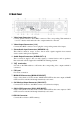
Menu Search Escape Sequence Fold tools Fast backward Fast forward Step forward Unfold tools Play/Pause Stop Copy Alarm reset Live/Playback PTZ Full screen Volume Page up Page down Close Motion detection setup Move the cursor to Menu-> -> Setup-> -> Camera-> -> Motion setting-> Detection setting. Move the cursor to screen below, the icons of motion detection will be displayed.
Set/Reset Set/Reset highlighted area whole area Sensitivity Test PTZ setup The function is as follows in the PTZ controls the appearance Go to Figure down Zoom Figure up Preset Focus Auto Focus Iris Auto pan Speed Mark position SEQ Video adjustment icons This camera default All camera default 72 Default
Common icons Up Down Enter Code Left Right Delete Back space Confirmed Space Mark Reduce/Add Numeral key 73
Appendix C – Specifications O.S. System Multiplex Certification Format Input Main monitor Video Main-AUX Call monitor Call-AUX Loop-through Loss detection Motion detection Input Audio Output Compression Record Display Playback Frame rate (IPS) & Resolution Mode Pre-record time Post-record time Resolution Split windows Frame rate Freeze Sequential switch Digital Zoom Frame rate (IPS) & Resolution Search Operation HDD Storage Partitions Backup Embedded Linux 2.
Alarm Network Control Setup Reliability Input Output Buzzer Triggered by Event log Ethernet Web E-mail Video Audio Protocol Remote users Bandwidth Remote stations I/R RS-232 RS-485 / RS-422 Local Remote Multi-lingual System recovery Timer Watch Dog Security Weights & Dimension Measures Weight Source Power Consumption Operating Temperature 16 contact or TTL/CMOS signal, polarity selectable 2 Normally Open, 2 Normally Closed relay output Yes Sensor input, Video loss, & Motion Yes 1 RJ-45 10/100BaseT Et
Appendix D – Recording Table NTSC Recording Time (in Hour) - For Reference Only System Storage (GB): 200 Average Resolution Recording Rate (IPS) Quality Picture Size (KB)* 120 60 30 15 10 5 720x480 9 32.2 58 115 173 345 (Full D1) 8 27.7 67 134 201 401 7 21.0 88 176 265 529 6 18.4 101 201 302 604 5 14.0 132 265 397 794 4 11.3 164 328 492 983 3 7.7 241 481 722 1443 2 5.6 331 661 992 1984 1 3.6 514 1029 1543 3086 720x240 9 16.
PAL Recording Time (in Hour) - For Reference Only System Storage (GB): 200 Average Resolution Recording Rate (IPS) Quality Picture Size (KB)* 100 50 25 12.5 8 4 720x576 9 42.0 53 106 165 331 (Full D1) 8 36.0 62 123 193 386 7 27.3 81 163 254 509 6 21.3 104 209 326 652 5 18.3 121 243 379 759 4 14.7 151 302 472 945 3 10.0 222 444 694 1389 2 7.3 304 609 951 1903 1 4.7 473 946 1478 2955 720x288 9 21.0 53 106 212 331 661 (Half D1) 8 18.
Via Don Arrigoni, 5 24020 Rovetta S. Lorenzo (Bergamo) http://www.comelit.it – E mail: export.department@comelit.