TM Installation Manual
Page 2 Installation Manual Contents Anatomy of a Fan --------------------------------------------------------------------------------------------------- 4 Check Your Shipment, What's Included For 6 Blade Fans --------------------------------------------------- 5 What You Need To Get Started ------------------------------------------------------------------------------------- 5 Check Your Shipment, What's Included For eco6 Guard Fan ---------------------------------------------------- 6 1 Important Informat
Page 3 2 Installation Procedures ----------------------------------------------------------------------------------------------------- 12 Step 1, Install Mounting Hardware ------------------------------------------------------------------------------- 12 Step 2, Attach Power Unit To Mounting Hardware --------------------------------------------------------------- 13 Step 3, Attach Safety Cable -------------------------------------------------------------------------------------- 13 Step 4, Mount The Motor C
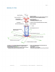
Page 4 Anatomy of a Fan MacroAir, Inc. www.macroairfans.
Page 5 Check Your Shipment, What's Included For 6 Blade Fans Note: Some models may vary slightly Blade Boxes Blade Carton (Blades) Power Unit Carton Remote Control Box (where applicable) Motor Control Panel with Variable Frequency Drive (where applicable) Owner's Manual with Warranty Card Installation Manual Gearbox Vent Cap (For Dodge Only) Power Unit (all preassembled) Hybrid Hub with H Beam Blade Struts Frame Gearbox Motor with J-Box Safety System Power Unit Carton Universal Mounting Hardware Swive
Page 6 Check Your Shipment, What's Included For eco6 Guard Fan Eco6 Guard Fan Motor Mount Assembly Motor/gearbox, Hybrid Hub, and keyless bushing adapter attached to motor mount If ordered without safety screens, the Hybrid hub cover, hub safety system, and blade struts will also be attached to the hub. Wall Mount Assembly V-shaped (roughly) wall mount Pivot mount (attached to wall mount) If the fan is ordered with screens, the following will be in the box.
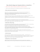
Page 7 Please Read this Important Information Before you Install Fans • Make sure Power is OFF before beginning any installation or maintenance procedure. • Refer to the enclosed packing list and verify that all fan components are included before you begin. 1.1 Key Safety System Components MacroAir fans are engineered with key safety features to prevent pieces of the fan from falling in the unlikely event of a catastrophic failure.
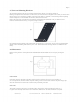
Page 8 1.5 Sprinkler Systems and Fan Placement In any installation where fire sprinklers are in place, do not interfere with their correct operation. Fans should be located not less than 3 feet below a sprinkler, and placed central to each sprinkler quadrant. Our standard variable-speed control system can be connected to a fire suppression control system, which will emergency-stop fans in case of fire.
Page 9 2.1 Weight A standard 1-horsepower 24 foot 6-blade fan weighs about 240 pounds, including the standard mounting hardware. In inverted-blade applications designed to blow air upward (very unusual), there is an additional down force of about 100 pounds due to fan thrust. We recommend that a building structure be capable of holding approximately twice the stated hanging weight of the fan.
Page 10 2.7 Universal Mounting Hardware We recommend mounting the fan to a horizontal structural beam, but this is not always possible in buildings with pitched roof construction. For that reason, our universal mount is designed to swivel freely in order to allow the fan to hang in a level position regardless of the angle of the beam it is mounted to. Our mounting hardware package includes clamps for use with standard steel I-beams, shims for thicker steel Ibeams, and all necessary nuts and bolts.
Page 11 Mounting Hardware Check all mounting bolts annually to be sure they have not loosened. Also, check the safety cable and guy wires to be sure they are not loose or frayed. Loose guy wires are more likely to break than tight ones, and broken guy wires may fall into the fan. If a guy wire is loose, carefully check to be sure it is not dam- aged, and retighten it. Blades Wipe any accumulated dust off all surfaces of the blades once a year. If needed, use a mild detergent solution.
Page 12 2 Installation Procedures Step 1, Install mounting hardware A) For glulam installations, attach the glulam brackets to the beam using ½" through bolts, not supplied. Note, ½" lag screws, also not supplied, may be used as an alternative, but will not provide as much mounting strength. Be sure the brackets line up with each other and that the bottom of each bracket is flush with the bottom of the beam.
Page 13 Step 2, Attach Power Unit To Mounting Hardware A) We recommend using a scissor lift to install our fans. The best method is to place the power unit hub-down on the lift and raise the lift until the power unit frame touches the bottom of the universal mount or extension (if used). B) Once the motor frame is in contact with the mount/extension, maneuver the power unit as necessary to line up the mounting holes.
Page 14 B) C) The MCP should be mounted at least 5 feet outside of the swept area of the fan blades; this will allow safe operation of the fan and still provide access to the MCP when the fan is running. Be sure to keep the lockable service disconnect located on the side of the MCP within line of sight of the fan motor to comply with OSHA and local safety codes. Mount the MCP, making sure the enclosure is firmly fixed to the mounting surface.
Page 15 Step 7, Make Motor Lead Connections A) Verify controller voltage; this can be found on the lower left corner of the MCP's door, as well as the sticker on the side of the VFD (see "input"). B) Use only the supplied motor cable for motor leads, and be sure to attach all four wires — three for power, one for ground. The 25 foot cable is recommended to prevent voltage and frequency fluctuations, which could cause the motor to malfunction and/or be damaged.
Page 16 E) Twist the three uninsulated stranded copper ground wires together (see figure 7) and connect them to the green ground screw located inside of the motor junction box. Fig 7 F) Wire motor leads for the appropriate voltage, referring to the wiring diagram on the motor's information label/plate or to Figure 8. Note that the top four diagrams are for U.S. motors, while the bottom two are for CE motors, usually for use outside the U.S.
Page 17 Step 8, Install Guy Wires If an extension is installed, be sure to use the longer guy wires packaged with it. Be sure to use four guy wires, with two clamps per end (four per guy wire). Keep the angle formed by the guy wire and the ceiling less than 45 degrees. If longer guy wire is required, it is available inexpensively at most hardware stores. Eye bolts (not supplied) are recommended to attach the wires to the building structure.
Page 18 1) Attach the tool to a 3/8 inch drive ratchet. 2) Loop the tool through the free end of the guy wire between the clamps and turn clockwise as far as possible. 3) Tighten the inner clamp to hold the tension. 4) Repeat until all excess slack is out of the wire. vi) Loosen the outer cable clamps, pull the slack out of the free end of the wire, and position the clamp about 18 inches from the inner one. vii) Re-tighten the outer clamp and double-check that the inner clamp is tight.
Page 19 B) Install extended blade safety links . This step is REQUIRED — omitting it will void manufacturer's warranty! Fig 12 C) i) On top of one blade, place a safety link, so the long leg lines up with the holes in the blade. Put a bolt through the outer blade hole just to hold the link in place — don't put a nut on it at this point, though. ii) On top of the next blade, place a second safety link so that the short end is on top of the previous safety link. (See Figure 2 above).
Page 20 Step 11, Install Guards If Necessary Refer to Section 2.6 on page 10 for guidelines. Step 12, Install Input Power A) Verify that input power voltage and number of phases match that of the MCP. B) Determine the appropriate size for the input circuit by multiplying the maximum input amperage of the VFD — found on the door of the MCP and on the included control panel schematic (wiring diagram) — by the number of fans to be placed on the circuit.
Page 21 F) If the fan is turning the wrong way on initial startup, follow the procedure below: i) Verify that the For-Off-Rev switch is in the For position. ii) If so, turn the switch to the Off position. iii) Carefully remove the remote switch box faceplate with the switches attached and turn it over. Verify that the wiring to the For-Off-Rev switch matches the wiring diagram (there should be a sticker inside the remote enclosure). If it's wrong, correct it and re-test the fan.
Page 22 3 Installation Procedures For eco6 Guard Fan Step 1, Install Mounting Assembly For Wall-Mounted Applications Fig 14 A) Mark a level line on the wall at the desired mounting height to locate the top edge of the upper mount plate. B) Use the mount as a template to carefully mark the locations of the mounting holes on the wall. There should be six holes total: four in the upper plate and two in the lower plate. Be sure to align the top edge of the upper mount plate with your level line.
Page 23 For Pole-Mounted Applications Fig 15 A) B) Cut and mount bracketing. i) Cut and assemble UniStrut or equivalent bracketing (not included). Use the mount assembly as a template for length and hole spacing. ii) Securely attach the brackets to the pole at the desired height. Be sure that all strap bolts are firmly tightened and that the vertical spacing is correct. Attach the fan to the bracketing. i) Insert 1/2" bolts with 1 washer each into the brackets.
!
!
!
!
!
!
!