
Specification Sheet

Shenzhen Macroreer E-Business CO., LTD.
3/F, Building 57, DaYun Software Park, 20140806
HenGang ST, LongGang District, Shenzhen, P.R.C Zipcode: 518000 Ver.:1.0
Tel: +86-755-85210544 Fax: +86-755-85210544
http://www.macroreer.com Email:marketing@macroreer.com
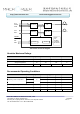
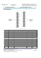
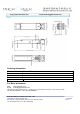
16 V
CCT
Transmitter Power Supply 2
17 V
EET
Transmitter Ground 1
18 TD+ Transmit Data In 3 Note 5
19 TD- Inv. Transmit Data In 3 Note 5
20 V
EET
Transmitter Ground 1
Notes:
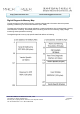
Plug Seq.: Pin engagement sequence during hot plugging.
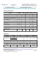
1) TX Fault is an open collector output, which should be pulled up with a 4.7k~10kΩ resistor on the host board to a voltage
between 2.0V and Vcc+0.3V. Logic 0 indicates normal operation; Logic 1 indicates a laser fault of some kind. In the low
state, the output will be pulled to less than 0.8V.
2) Laser output disabled on TDIS >2.0V or open, enabled on TDIS <0.8V.
3) LOS is open collector output. Should be pulled up with 4.7k~10kΩ on host board to a voltage between 2.0V and 3.6V.
Logic 0 indicates normal operation; logic 1 indicates loss of signal.
4) RD-/+: These are the differential receiver outputs. They are internally AC-coupled 100 differential lines which should be
terminated with 100Ω (differential) at the user SERDES.
5) TD-/+: These are the differential transmitter inputs. They are internally AC-coupled, differential lines with 100Ω differential
termination inside the module.
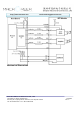
Recommended Interface Circuit