Macurco™ CM-12 Carbon Monoxide Detector, Controller and Transducer User Instructions Important: Keep these User Instructions for reference
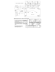
TABLE OF CONTENTS GENERAL SAFETY INFORMATION Intended Use List of Warnings and Cautions USE INSTRUCTIONS AND LIMITATIONS Use For Do Not Use For General Description Features Specifications INSTALLATION AND OPERATING INSTRUCTIONS Location Connections Installation 4-20 mA Output diagram Rear View Image Alarm Control Panel diagram Multiple Device diagram Alternate Alarm Panel diagram DVP-120 Control Panel diagram Power Up Operation Default - Factory Settings Display setting Buzzer setting Alarm Relay setting Al
GENERAL SAFETY INFORMATION Intended Use The Macurco CM-12 is a line voltage, dual relay Carbon Monoxide (CO) detector, controller and transducer. The CM-12 utilizes an internal switching power supply that is capable of using line voltage between 100 and 240VAC and 50-60Hz. The CM-12 has selectable 4-20 mA output, buzzer and digital display options.
USE INSTRUCTIONS AND LIMITATIONS ! WARNING Each person using this equipment must read and understand the information in these User Instructions before use. Use of this equipment by untrained or unqualified persons, or use that is not in accordance with these User Instructions, may adversely affect product performance and result in sickness or death.
Features ETL Listed to UL 61010-1 and CAN/CSA C22.2 No 61010-1 Low level meter capable of displaying from 0-200 ppm of CO The CM-12 meets the Uniform Building Code for enclosed garages and meets OSHA standards for CO exposure Selectable fan and alarm relay activation 5 A SPDT fan relay controls starters of exhaust fans 0.5 A N.O. or N.C.
! WARNING This detector helps monitor for the presence and concentration level of a certain specified airborne gas. Misuse may produce an inaccurate reading, which means that higher levels of the gas being monitored may be present and could result in overexposure and cause sickness or death. For proper use, see supervisor or User Instructions, or call Technical Service at 1-877-367-7891. Location A CM-12 is normally mounted at breathing level, about 5 feet (1.
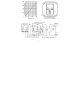
approximately 1/4 in. (6.5 mm), insert the bare wire into the terminal and tighten the screw clamp. Ensure that the wire cannot easily be pulled from the connector. When the wires are connected seat the modular connector into the header ensuring that the latch engages. 4-20mA Signal Connection The positive and negative 4-20mA signal connections (+ and -) are available at the 4-20mA modular connector, a 2-position connector.
Typical connection to the Macurco DVP-120 Detection and ventilation Control Panel Power Up The CM-12 cycles through an internal self-test cycle for the first minute that it is powered. The unit will execute the test cycle any time power is dropped and reapplied (i.e. power failure). During the self-test cycle the unit will display the firmware version number, then count down from 60 to 0 (if the display setting is “On”) and finally go into normal operation.
Default Configuration – Factory Settings The default Power Up Test setting is On The default Display setting is Off The default Buzzer setting is Off The default Alarm Relay Setting is activation at 200 ppm The default Alarm Relay Configuration setting is Normally Open The default Fan Relay Setting is activation at 35 ppm The default Fan Relay Delay setting is 3 minutes The default Fan Relay Runtime setting is 0 The default Fan Relay Latching condition is OFF The defau
Selecting Power Up Test Option – “PUt” To select the Power Up Test Configuration, in normal mode, push the Next button to get to “Con” or the Configuration menu. Then push the Enter button to enter the Con menu. Then push the Next button to get to the second selection “PUt” or Power Up Test setting. Push Enter. If the testis “On” push Next to turn it “OFF” (flashing) then push Enter to confirm the change (solid) and push Enter again to return to “PUt” in the Con menu.
(solid) and push Enter again to return to “FrD” in the Con menu. Push Next until “End” is displayed then push Enter to get back to normal operation. Selecting Fan Relay Runtime – “Frr” To select the Fan Minimum Runtime setting, in normal mode, push the Next button to get to “Con” or the Configuration menu. Then push the Enter button to enter the Con menu. The ninth selection is the “Frr” or Fan Minimum Run Time. Push Next seven times to get to “Frr” then Enter.
Error Codes t01 t02 t04 t08 t10 t20 t40 t80 t100 t200 Sensor is missing Temperature compensation failed Bad EEPROM checksum Sensor is shorted Bad EEPROM Bad calibration Factory calibration was not done ADC reading failed Under range sensor Sensor expired NOTE: For trouble codes over 080 the display will alternate between t_1 and t00 for t100 and between t_2 and t00 for t200. If the error mode repeats frequently, check for continuous power and proper voltage.
Sensor Life Reset 1. Remove the Philips screw on the front of the CM-12. Pull the front cover of the unit off. 2. To reset the sensor life (rSt), from normal or warm-up mode, press the Next button four times to get to “SEn” or Sensor Mode. 3. Then press the Enter button to get to “rSt” - Reset Sensor Mode. 4. Press the Enter button again to see the sensor reset status. If the sensor life has already been reset, done “don” will be displayed. If it has not already been reset, “no” will be displayed.
display the error code, the green status indicator LED light will flash and the buzzer will chirp intermittently. The Fan relay will also engage if the Trouble Fan Setting Option is set to “ON”. Operation Test Check that the green CM-12 status indicator LED light is illuminated continuously. If not, do not proceed with the tests. If the unit is in error mode contact your local representative or Macurco technical service representative for information on resolving the problem. 1.
Carbon Monoxide Gas Test ! WARNING The following steps must be performed when conducting a calibration or calibration verification test (bump test) to ensure proper performance of the monitor. Failure to do so may adversely affect product performance and result in sickness or death. When performing a calibration or calibration verification test (bump test) only use certified calibration gas at the required concentration level. Do not calibrate with expired calibration gas.
Gas Testing Testing the Fan Relay 1. 2. 3. 4. Remove the Philips screw on the front of the CM-12. Remove the front cover. Open the FCK. Connect the 50 ppm gas cylinder to the regulator. Check the pressure gauge on the regulator. If you have 25-psi or less you will need to replace the gas canister. Assemble regulator, hose and Test Hood and place the Test Hood over the CO sensor. Note: The time to activate the Fan relay depends on the delay setting. 5. 6.
Testing the 4-20mA current loop 1. 2. 3. 4. 5. 6. Connect the 200 ppm cylinder of carbon monoxide to the regulator. Check the pressure gauge. If there is 25-psi or less the cylinder should be replaced. Place the cap from the regulator over the CO sensor. Turn on the regulator to start the gas flow. The Fan relay should activate according to the settings. The Alarm relay should activate according to the settings. The 4-20 mA output should ramp up from 4mA in clean air to 20mA at 200 ppm.
3. Check the pressure gauge on the regulator. If you have 25-psi or less you will need to replace the gas canister. 4. Place the test Hood from the regulator over the CO sensor. 5. Push Next 3 times to get to the CAL menu then push Enter. The display will flash back and forth between GAS and 200. 6. Start applying gas to the CO sensor. Note: The sensor will look for the gas for 45 seconds. If no gas is applied or detected in that time, the display will return to CAL. 7.