Macurco™ Ammonia Detector, Controller and Transducer TX-6-AM User Instructions Important: Keep these User Instructions for reference
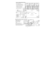
TABLE OF CONTENTS GENERAL SAFETY INFORMATION Intended Use List of Warnings and Cautions USE INSTRUCTIONS AND LIMITATIONS Use For Do Not Use For General Description Features Specifications INSTALLATION AND OPERATING INSTRUCTIONS Location Installation Garage diagram 4-20 mA Output diagram Multiple Device diagram Alarm Control Panel diagram DVP-120 Control Panel diagram Alternate Alarm Panel Power Up Operation Default – Factory Settings Display setting Buzzer setting Alarm Relay setting Alarm Relay Configurati
GENERAL SAFETY INFORMATION Intended Use The Macurco TX-6-AM is a low voltage, dual relay Ammonia (NH3) detector, controller and transducer. The TX-6-AM has selectable 420 mA output, buzzer and digital display options. It is an electronic detection system used to measure the concentration of NH3 and provide feedback and automatic exhaust fan control to help reduce NH3 concentrations in industrial refrigeration, warehouses, hockey rinks or other commercial applications.
USE INSTRUCTIONS AND LIMITATIONS ! WARNING Each person using this equipment must read and understand the information in these User Instructions before use. Use of this equipment by untrained or unqualified persons, or use that is not in accordance with these User Instructions, may adversely affect product performance and result in sickness or death.
Features Specifications ETL Listed to UL 61010-1 Low level meter capable of displaying from 0-100 ppm Ammonia The TX-6-AM meets NIOSH and OSHA standards for gas exposure Selectable fan and alarm relay activation 5 A SPDT fan relay controls starters of exhaust fans 0.5 A N.O. or N.C.
! WARNING This detector helps monitor for the presence and concentration level of a certain specified airborne gas. Misuse may produce an inaccurate reading, which means that higher levels of the gas being monitored may be present and could result in overexposure and cause sickness or death. For proper use, see supervisor or User Instructions, or call Technical Service at 1-877-367-7891.
8. The Fan Relay can be configured for latching or non-latching (default) when activated (when the gas concentration exceeds fan relay set point). 9. The Fan Relay will engage if the fan setting Ammonia concentration is exceeded for longer than the Fan Relay Delay time.
Power Up The TX-6-AM steps through an internal self-test cycle for the first 1 minute that it is powered. The unit will execute the test cycle any time power is dropped and reapplied (i.e. power failure). During the self-test cycle the unit will display the Firmware Version number, then count down from 60 to 0 and finally go into normal operation. The Fan and Alarm relay will be activated for the power-up cycle unless the “Power Up Test” (PUt) option is OFF.
The default Buzzer setting is OFF The default Alarm Relay Setting is activation at 75 ppm The default Alarm Relay Configuration is Normally Open The default Fan Relay Setting is activation at 25 ppm The default Fan Relay Delay setting is 3 minutes The default Fan Relay Runtime setting is 0 The default Fan Relay Latching condition is OFF The default 4-20mA Output setting is On To change settings, remove the Philips screw on the front of the TX-6-AM.
Selecting Power Up Test Option – “PUt” To select the Power Up Test Configuration, in normal mode, push the Next button to get to “Con” or the Configuration menu. Then push the Enter button to enter the Con menu. Then push the Next button to get to the second selection “PUt” or Power Up Test setting. Push Enter. If the test is “On” push Next to turn it “OFF” (flashing) then push Enter to confirm the change (solid) and push Enter again to return to “PUt” in the Con menu.
(flashing) then push Enter to confirm the change (solid) and push Enter again to return to “FrS” in the Con menu. Push Next until “End” is displayed then push Enter to get back to normal operation. Selecting Fan Relay Delay – “Frd” To select the Fan Relay Delay setting, in normal mode, push the Next button to get to “Con” or the Configuration menu. Then push the Enter button to enter the Con menu. The eighth selection is the “Frd” or Fan Relay Delay. Push Next seven times to get to “FrD” then Enter.
The 4-20 mA signal can be used for troubleshooting: 0 mA is most likely a connection problem 4-20 mA is normal gas reading range (0-100 ppm) 24 mA indicates a Trouble condition Error Codes t01 Sensor is missing t02 Temperature compensation failed t04 Bad EEPROM checksum t10 Bad EEPROM t20 Bad calibration t40 Factory calibration was not done t80 ADC reading failed t100 Under range sensor t200 Sensor warranty expired NOTE: For trouble codes over 080 the display will alternate between t
The end-of-warranty signal can be silenced for 48 hours by pressing the "ENTER/TEST" button or by temporarily dropping power to the unit. The end-of-warranty signal provides the user an opportunity to test and/or calibrate the sensor assuring that it is still performing within acceptable parameters though the sensor is nearing the end of its 2-3 year expected life. The silence function will continue to be available for 29 days after the TX-6-AM initiates the initial end-of-warranty signal.
Do not disassemble unit or attempt to repair or modify any component of this instrument. This instrument contains no user serviceable parts, and substitution of components may impair intrinsic safety, which may adversely affect product performance and result in sickness or death. CAUTION Avoid the use of harsh cleaning materials, abrasives and other organic solvents. Such materials may permanently scratch the surfaces and damage the display window, labels, sensor or instrument housing.
7. Push the Test switch once. 8. The TX-6-AM will step through a cycle test: 9. a) The display progresses through the BUZ (buzzer test), Art (alarm relay test), Frt (fan relay test) then 42t (4-20 mA output test). b) During the first 3 seconds of the test cycle, the Buzzer will sound c) During the next 5 seconds of the test cycle, the Alarm relay will be closed, so any devices connected to that relay will be tested.
Ammonia Gas Test ! WARNING The following steps must be performed when conducting a calibration or calibration verification test (bump test) to ensure proper performance of the monitor. Failure to do so may adversely affect product performance and result in sickness or death. When performing a calibration or calibration verification test (bump test) only use certified calibration gas at the required concentration level. Do not calibrate with expired calibration gas.
5. 6. Turn on the regulator to start the gas flow and wait with the gas applied continuously. With the display function turned “On”, the TX-6-AM will show the current concentration of gas or “0” (zero) in clean air. When the gas concentration reaches the Fan Relay setting (20 ppm, for example) the display will flash back and forth between “FAn” and “20”. With the display function turned ”OFF”, the display does not show the gas concentration, but will show “FAn” as long as the fan relay is activated.
Note: If the Alarm relay fails to operate within 2 minutes, there are four possibilities: a. b. c. d. 6. Gas cylinder is empty, check the pressure gauge. Replace the gas cylinder if 25-psi or less. Unit needs to be re-calibrated (go through recalibration and re-test). Detector is in need of servicing (return unit to factory for servicing). Detector has Alarm relay set to disable (diS) or higher than 20. Set Alarm relay to 20 ppm and repeat the test. Remove the gas from the sensor after Test.
6. If the process was not successful the display will read the current gas level alternating with FAil (fail) (blinking). If this occurs, repeat steps 2 through 4. If the sensor fails to zero twice contact Technical Assistance: 1-877-367-7891. Note: The display may just go back to 000 if the process is unsuccessful because the sensor response is too negative or if gas is present. 7. To return to Normal Mode press Enter and then press Next until “End” is displayed. Press Enter to return to Normal Mode.
MACURCO FIXED GAS DETECTION PRODUCTS LIMITED WARRANTY Macurco warrants the TX-6-AM gas detector will be free from defective materials and workmanship for a period of two (2) years from date of manufacture (indicated on the inside cover of the TX-6-AM), provided it is maintained and used in accordance with Macurco instructions and/or recommendations.