
User Instructions


16
Do not disassemble unit or attempt to repair or modify any component of this instrument. This instrument contains no user serviceable
parts, and substitution of components may impair intrinsic safety, which may adversely affect product performance and result in
sickness or death.
CAUTION
Avoid the use of harsh cleaning materials, abrasives and other organic solvents. Such materials may permanently scratch the surfaces
and damage the display window, labels, sensor or instrument housing.
Cleaning
Cleaning of the external surfaces is best carried out using a damp cloth with a mild detergent or soap. Use a vacuum cleaner with soft
brush to remove dust or contamination under the cover. Do not blow out the sensor with compressed air.
TESTING
Using a certified gas with a concentration other than the one listed for this detector when conducting a calibration or calibration
verification test (bump test) will produce inaccurate readings. This means that higher levels of the gas being monitored may be present
and could result in overexposure and cause sickness or death. For proper use, see supervisor or User Instructions, or call Technical
Service at 1-877-367-7891
General
All TX-6-AM units are factory calibrated and 100% tested for proper operation. The unit also performs a regular automatic self-test
during normal operation. If the unit detects an improper voltage or inoperable component, it will default into Error mode. In this error
mode, the Fan and Alarm relays will be activated, the 4-20 mA output will go to 24 mA, the unit will display the error code and the
buzzer will chirp intermittently.
Operation Test
Normally this will be the only test required for the TX-6-AM and is the recommended way to test the unit or units after installation. Check
that the green TX-6-AM operating LED light is illuminated continuously. If not, do not proceed with the tests. If the unit is in error mode
contact your local representative or Macurco technical service representative for information on resolving the problem.
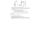
1. Remove the single screw in the middle of the front cover of the TX-6-AM.
2. Remove the front cover.
3. Locate the switch labeled ENTER/TEST on the left side of the printed circuit board.
4. Observe the LED light on the front of the TX-6-AM.
5. If the light is solid green proceed to step 7.
6. If the light is off or flashing Green, refer to the General section above.
! WARNING