DYNA-GLASTM CENTRIFUGAL PUMPS WITH INTEGRAL TRAP O W N E R’ S M A N U A L INSTALLATION, OPERATION & PARTS 5MPRA Series MODELS 5MPRA6C-146 5MPRA6D-147 5MPRA6E-148 5MPRA6F-156 5MPRA6C3-146 5MPRA6D3-147 5MPRA6E3-148 5MPRA6F3-156 This manual should be furnished to the end user of this pump; its use will reduce service calls and chance of injury and will lengthen pump life. STA-RITE FOREIGN SALES CORP.
‘5MPRA’ SERIES PUMP WITH TRAP To avoid unneeded service calls, prevent possible injuries, and get the most out of your pump, READ THIS MANUAL CAREFULLY! The Sta-Rite ‘5MPRA’ Series Self-priming Centrifugal pump: • Is designed for use with swimming pools or as a centrifugal pump. • Is an excellent performer; durable, reliable. Table of Contents Warranty.......................................................................................................2 Safety Instructions ................................
IMPORTANT SAFETY INSTRUCTIONS Always follow basic safety precautions with this equipment, including the following. To reduce the risk of injury, do not permit children to use this product unless they are closely supervised at all times. This pump is for use with permanently installed pools and may also be used with hot tubs and spas if so marked. Do not use with storable pools.
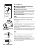
DISCHARGE PORT TO FILTER OR POOL NOTICE: Port threads are: Internal - 2" NPT for direct connection to pipe. External - 3-1/4" Buttress. Fits Sta-Rite U11-200P Union Half for quick disconnect pipe connection. STRAINER BASKET COVER SUCTION PORT FROM POOL OR VACUUM FILTERS Figure 1 PUMP MAY BE BOLTED TO LEVEL FOUNDATION OR MOUNTING BRACKET INSTALLATION Only qualified, licensed personnel should install pump and wiring. Pump mount must: Be solid - Level - Rigid - Vibration free.
Piping: Use at least 1-1/2" (38mm) pipe (use 2"(51mm) pipe if possible). Increase size if a long run is needed. When using 1-1/2" pipe, connect to pump with 1-1/2" to 2" (38 to 51mm) reducing adapter. To avoid strains on the pump, support both suction and discharge pipes independently. Place these supports near the pump. To avoid a strain left by a gap at the last connection, start all piping at the pump and run pipe away from the pump.
ELECTRICAL Ground motor before connecting to electrical power supply. Failure to ground motor can cause severe or fatal electrical shock hazard. Do not ground to a gas supply line. To avoid dangerous or fatal electrical shock, turn OFF power to motor before working on electrical connections. Ground Fault Circuit Interrupter (GFCI) tripping indicates an electrical problem. If GFCI trips and will not reset, have a qualified electrician inspect and repair electrical system. Hazardous voltage.
OPERATION NOTICE: NEVER run pump dry. Running pump dry may damage seals, causing leakage and flooding. Fill pump with water before starting motor. Before removing trap cover: 1. STOP PUMP before proceeding. 2. CLOSE GATE VALVES in suction and discharge pipes. 3. RELEASE ALL PRESSURE from pump and piping system. If pump is being pressure tested, be sure pressure has been released before removing trap cover. Do not block pump suction. To do so with body may cause severe or fatal injury.
Drain all water from pump and piping when expecting freezing temperatures or when storing pump for a long time (see instructions below). Keep motor dry and covered during storage. To avoid condensation/corrosion problems, do not cover pump with plastic. For outdoor/unprotected installations: 1. Enclose entire system in a weatherproof enclosure. 2. To avoid condensation/corrosion damage, allow ventilation; do not wrap system in plastic. 3.
PUMP SERVICE Pump should only be serviced by qualified personnel. Be sure to prime pump (Pg. 7) before starting. Before removing trap cover: 1. STOP PUMP before proceeding. 2. CLOSE GATE VALVES in suction and discharge pipes. 3. RELEASE ALL PRESSURE from pump and piping system. To avoid dangerous or fatal electrical shock hazard, turn OFF power to motor before working on pump or motor.
Pump Reassembly/Installing New Seal 1. Ceramic seat must be clean and free of dirt, grease, dust, etc. Wet outer edge with small amount of liquid detergent; press ceramic seat into seal plate cavity firmly and squarely with finger pressure (Fig. 6). 2. If ceramic seat will not locate properly, remove it, place face up on bench and reclean cavity. Ceramic seat should now locate. 3.
Clogged pipe/trap/impeller, worn impeller: 7. Make sure suction trap is not clogged; if it is, clean trap and strainer. 8. Make sure impeller is not clogged (follow steps 1 through 7 under “Removing Old Seal”, Page 9; check impeller for clogging; follow steps 7 through 11 under “Installing New Seal”, Page 10, for reassembly). 9. Impeller and diffuser may be worn. If so, order replacement parts from Repair Parts List, Page 12. Electrical: 10.
1 2 3 BOX A 4 For quick disconnect pipe connection parts: 5 6 7 Box A 8 8A 8B Adapter Union Pkg ..................... 11201-0153 12 9 10 23 O-Rings (2) .................... 35505-1318 13 14 22 21 11 20 15A 19 Box A 18 17 16 15B REPAIR PARTS LIST DYNAGLAS POOL PUMP 1/2 through 1-1/2 HP Models Key No.