Owner’s Manual MP-8 MP-9 Projectors
C A U TI O N RISK OF ELECTRIC SHOCK DO NOT OPEN CAUTION: TO REDUCE THE RISK OF ELECTRIC SHOCK, DO NOT REMOVE COVER (OR BACK). NO USER-SERVICEABLE PARTS INSIDE. REFER SERVICING TO QUALIFIED SERVICE PERSONNEL. The lightning flash with arrowhead symbol, within an equilateral triangle, is intended to alert the user to the presence of uninsulated “dangerous voltage” within the product’s enclosure that may be of sufficient magnitude to constitute a risk of electric shock to persons.
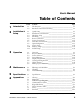
User's Manual Table of Contents Section Contents Page 1 Introduction 1.1 1.2 The Projector ________________________________________ 1.1 Purchaser's Record and Servicing _________________________ 1.2 2 Installation & Setup 2.1 2.2 2.3 2.4 2.5 2.6 2.7 2.8 2.9 2.10 2.11 Quick Setup _________________________________________ 2.1 Installation Considerations ______________________________ 2.2 Hardware Setup ______________________________________ 2.8 Mounting __________________________________________ 2.
Section 1 Introduction 1.1 The Projector The Madrigal Imaging MP-8 and MP-9 projectors are ultra high resolution graphics projectors compatible with virtually all input sources. Their superior performance and high quality projected images place them well above other projection systems in their class.
INTRODUCTION Should projector servicing be required, service personnel can use the keypad to make service adjustments and alignments. In some cases the projector may be serviced without accessing the projector’s internal circuitry. Projector settings, usually different for different sources, are stored in memory for each individual source. These settings are retained until changed by the user, even if power is removed from the projector.
Section 2 Installation & Setup This section explains how to install and set up the projector. If you are familiar with the projector and want to quickly set it up for temporary use, follow the Quick Setup instructions in section 2.1. For a complete setup, skip section 2.1 and follow the instructions and guides covered in the remaining subsections. 2.
INSTALLATION & SETUP Step 6 ➤ Select the Input Press Step 7 ➤ Installation Type ➤ 1 to select the source connected to the built-in RGB input. Adjust the Display Press 2.2 Installation Considerations 0 SOURCE HELP 0 to select the Guided Source Setup tutorial. Careful consideration should be given as to how and where the projection system is installed. Although the projector offers high performance, the final display quality will be compromised if the projector is not installed properly.
INSTALLATION & SETUP Rear Screen, Ceiling Mount Installation ADVANTAGES • Projector is completely hidden from the audience. • Usually good ambient light rejection. CONSIDERATIONS • Requires separate room. • Installation cost is usually higher. Rear Screen, Floor Mount With Mirror ADVANTAGES • Projector is completely hidden. • Usually good ambient light rejection. • Less space is required behind the screen than other rear screen installations. Screen Type ➤ CONSIDERATIONS • Requires separate room.
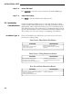
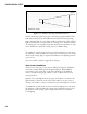
INSTALLATION & SETUP Curved Screen (gain >1) Audience Coverage Figure 2-2. Audience Coverage with Curved Screen Curved screens have gains larger than 1 and viewing angles much less than 180°. Most curved screens have different horizontal and vertical viewing angles. Incident light does not reflect equally in all directions. The reflected light concentrates in a conical volume or “viewing cone”. Audiences within the viewing cone see a brighter image than that from an equal area on a flat screen.
INSTALLATION & SETUP Screen Size and ➤ Throw Distance Screen size and throw distance are interrelated. (See Appendices F and G.) As screen size increases, the distance between the projector and the screen also increases. During projection room design, make sure that the room can accommodate the required position of the projector for the screen size you need. Screen Size Screen sizes vary according to model and lens type. (See Appendices F and G.
INSTALLATION & SETUP Lighting ➤ Proper lighting is another important factor when designing a projection room. Visiting a movie theatre can give you an idea of what makes a good projection environment. All walls, floors and furnishings are dull colored and non-reflectively finished. Every effort should be made to create the best environment for your system. When designing a projection room, try to avoid white, reflective ceilings and non-directional lighting such as fluorescent lights.
INSTALLATION & SETUP door Prime Audience Area door window Figure 2-4. Good Screen Placement Other ➤ Considerations Here are some other considerations and tips which can help you improve the design of your projection system. ❑ Proper ventilation is important. The ambient temperature should be kept constant and below 35° C (95° F). Keep the projector away from heating and/or air conditioning vents. Changes in temperature can cause drifts in the projector circuitry which may affect performance.
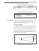
INSTALLATION & SETUP SQUARE ROOMS Corner placement of screen yields best audience coverage. RECTANGULAR ROOMS Screen placement along short wall yields best audience coverage. Prime Audience Area Prime Audience Area Figure 2-5. Screen Locations for Maximum Audience Coverage 2.3 Hardware Setup Keypad ➤ Conversion 2.
INSTALLATION & SETUP Follow the steps below to convert the keypad to a remote keypad and change its protocol setting. Step 1 Unplug the projector then lift the front top cover to access the built-in keypad. To lift the cover, grasp it above the red and blue lenses then lift it until the keypad is exposed. The keypad is mounted to a securing bracket located above the lens assemblies. Loosen the two bracket wing nuts then move the keypad away from the bracket. See Figure 2-6.
INSTALLATION & SETUP JP1 This jumper setting is important if the keypad is configured for remote operation. There are two keypad protocols: A and B. These protocols are available to allow two projectors in the same room to be independently controlled by separate remote keypads. The protocol setting of the keypad must 6 7 ). For match that set in the projector’s Keypad Options menu ( more information about keypad protocols, refer to the Remote Control Options entry in section 3.7, Utility Features.
INSTALLATION & SETUP If the keypad is configured for IR remote operation, make sure the batteries are installed. If it is configured for built-in or wired remote operation, make sure its extension cable is properly connected to the projector. Perform the following keystroke sequences to change its operating settings: • To toggle the keypad’s protocol setting (A or B), 1 . press BRITE TINT DETAIL • To toggle the backlit feature (enable or disable), 3 .
INSTALLATION & SETUP 2.4 Mounting Front Screen ➤ Installations The projector should be mounted after the system design has been established and reverse scan setup (if required) is complete. Floor Mount Mount the projector on a secured table or cart. Position the projector at the chosen room location with the projector pointing towards the center of the projection screen.
INSTALLATION & SETUP Position the projector so that it is pointing toward the center of the projection screen. The angle of projection combined with the tilt angle of the screen should direct the reflected image towards the center of the audience. It is recommended that the difference between the projection angle and the screen tilt angle (within a common reference) be less than 15°. See to Figure 2-11. Figure 2-11.
INSTALLATION & SETUP Diffused Rear Screen Systems If the system includes a diffused rear screen, floor mount or ceiling mount the projector so that the image is directed to the center of the audience. Projection tilt should be less than 15°. See Figure 2-13. Figure 2-13. Diffused Rear Screen Installation In situations where the space behind the projector is limited, a mirror may be used to fold the optical path as illustrated in Figure 2-14.
INSTALLATION & SETUP 2.5 Power Connection To apply power to the projector, plug the AC line cord into the line input socket located at the front panel of the projector. Plug the three prong end of the line cord in a grounded AC outlet. Input voltage to the projector must be between 90 and 264 VAC, 50 or 60 Hz. The power source must supply 650 watts of power to the projector. 90 - 264 VAC 50 - 60 Hz Figure 2-15. Power Connection 2.
INSTALLATION & SETUP The RGB interface allows connection of an RGB source having one of the following sync types: sync on green, composite sync, or separate H & V sync. To connect a source, connect the red, green, and blue outputs to the RED, GREEN, and BLUE inputs on the interface. If the source uses sync on green, no additional cables are required. If the source provides a composite sync output, connect it to the HOR/COMP input.
INSTALLATION & SETUP Notes: 1) All serial connections require a 9 pin D connector at the projector end. Refer to Appendix D for cable wiring requirements. 2) For computer/controller control, PC software is required. 3) The RS-232 serial port labeled “OUT” is provided for projector networking applications. 2.8 Optical Alignment Optical alignment is required when the throw distance changes or the projector cannot be focused using the focus controls.
INSTALLATION & SETUP Step 2 ➤ Locate the front top cover of the projector. See Figure 2-19. Next, position your hands above the red and blue lenses then grasp the cover. Gently lift it until it is released from its securing latch. Slide the cover away from the projector as shown in Figure 2-20 below. Front Top Cover Foam Piece Figure 2-19. Front Top Cover a) Lift front cover until latch is released. b) Slide cover forward. Figure 2-20.
INSTALLATION & SETUP Top Plate Lens/CRT Securing Bolts A A D D A C C B A B Center Focus Adjust Corner Focus Adjust Blue Green Red Figure 2-21b. MP-8 Lens Assemblies - Top View For the MP-9: The lenses are secured to the projector frame by a top plate and individual mounting plates as shown in Figures 2-21a and 2-22a. During optical alignment, adjust the top plate securing bolts using the ball nose screw driver ( ) supplied with the projector.
INSTALLATION & SETUP Lens Mounting Plate Blue Green Red Top/Bottom Focus Adjust Left/Right Focus Adjust Factory/Service Adjust Only Figure 2-22b. MP-8 Lens Assemblies - Front View For the MP-9, each CRT is attached to its lens by socket head allen screws located at each lens mounting plate. For each lens, the upper left screws (when facing the lens) adjust the focus between the left and right sides of the picture, and the upper right screws adjust the focus between the top and bottom of the picture.
INSTALLATION & SETUP Step 7 ➤ Look directly into the green lens. Press , , or displayed crosshatch on the face of the picture tube. Step 8 ➤ Look directly into the blue lens. Press , , or to center the displayed crosshatch on the face of the picture tube. Step 9 ➤ Press to center the to increase contrast to a normal viewing level. Step 10 ➤ Pivot the projector and move it side to side as necessary to display a pivot point symmetrical crosshatch centered left-to-right on After Before the screen.
INSTALLATION & SETUP Step 16 ➤ Press Step 17 ➤ On the MP-9, loosen the three bolts labeled “B”. One is located on the top plate. The other two are below the red lens. or to adjust for best electrical focus at the center of the picture. B B G G R R On the MP-8, loosen the four bolts labeled “A”. Loosen the two bolts labeled “B”. Step 18 ➤ Step 19 ➤ A red and green crosshatch is displayed. Move the red lens so that the left and right edges of the red crosshatch match the green.
INSTALLATION & SETUP Step 22 ➤ On the MP-9, tighten the three bolts labeled “D”. B G B G R B G R B G R R On the MP-8, tighten the two bolts labeled “D”. Step 23 ➤ Step 24 ➤ A green image is displayed. Loosen the rear wing nut on the green lens and slightly defocus the center of the picture. On the MP-9, locate the two TOP Bolt adjustment bolts at the upper SIDE right corner of the green lens Bolt mounting plate (viewed from the front).
INSTALLATION & SETUP Step 26 ➤ A red image is displayed. Loosen the rear wing nut on the red lens and slightly defocus the center of the picture. B Step 27 ➤ On the MP-9, locate the two adjustment bolts at the upper right corner of the red lens mounting plate (viewed from the front). G R TOP Bolt SIDE Bolt R Before After Adjust the two bolts until the top and bottom areas of the picture are equally defocused. Use the same technique as that used for the green adjustment (step 24).
INSTALLATION & SETUP Step 30 ➤ A blue image is displayed. Loosen the rear wing nut on the blue lens and slightly defocus the center of the picture. B Step 31 ➤ On the MP-9, locate the two adjustment bolts at the upper right corner of the blue lens mounting plate (viewed from the front). G R TOP Bolt SIDE Bolt B Before After Adjust the two bolts until the top and bottom areas of the picture are equally defocused. Use the same technique as that used for the green and red adjustments.
INSTALLATION & SETUP Step 34 ➤ For the MP-9, optical alignment is now complete. If you had removed the foam insert, reinstall it now. Install the front top cover. Proceed to set up each source by following the source setup procedure in section 2.9, Source Setup. On the MP-8, tighten the bolts labeled “A”. Optical alignment is now complete. If you had removed the foam insert, reinstall it now. Install the front top cover. Proceed to set up each source by following the source setup procedure in section 2.
INSTALLATION & SETUP Step 4 ➤ Press or to adjust skew until the vertical line through the center of the image is not tilted (perpendicular to the horizontal line). Press or until the center horizontal line is perpendicular to the vertical. Step 5 ➤ Press or to adjust keystone until the width at the top of the picture is equal to the width at the bottom. Before Step 6 ➤ After Press or to adjust side pincushion until the left and right sides of the picture are straight and not curved.
INSTALLATION & SETUP Step 10 ➤ Adjust C linearity as follows: Press or until the horizontal line through the center of the crosshatch is equally distant from the lines at the very top and bottom. Before After Press or until the center of the crosshatch is equally distant from the vertical lines at the left and right edges. Step 11 ➤ Adjust S linearity as follows: Press or until the height of each crosshatch square is equal from the top to the bottom.
INSTALLATION & SETUP Step 14 ➤ The final step is convergence. If the projector includes the ACON option, 4 to exit the guide and allow ACON to converge the system. press 1 to enter Guided Convergence. Otherwise, press EXIT CONV EXIT CONV Reminder: Remember that all of the adjustments above should be repeated for other sources in the system. 2.10 Memory Setup This section explains how to set up projector memories to improve the performance of the projector’s ASI and ASR features.
INSTALLATION & SETUP About ASI and ASR ... ASI (Automatic Source Interpolation) is a feature which automatically adjusts display settings based on the settings of other setup memories stored in the projector. When a setup memory is first created, ASI automatically generates its initial display settings. These settings will be created by copying another setup memory or by interpolating multiple setup memories. ASI is activated when: • A new setup memory is created.
INSTALLATION & SETUP Recall Memory ➤ Setup Follow these steps to prepare a Recall memory. Step 1 Select the input connected to the source. For example, if the source is 1 5 . The source should be connected to switcher 1, slot 5, press displayed on the projection screen. SOURCE Note: To assure proper setup of a Recall memory, ASR must be off (default) for the current input. Step 2 Select a Recall memory as the current setup memory. For example, to make 0 3 .
INSTALLATION & SETUP Step 1 Select a Recall memory to be the current setup memory. For example, to 9 0 . (Recall make Recall memory 90 the current setup memory, press memory numbers may be any number from 01 to 99). If the selected Recall memory did not previously exist, it will be created automatically. RECALL Step 2 6 to access the Internal 1 Press Frequency Selection menu. Items one to six contain preset scan frequencies covering the scan range of the projector.
INSTALLATION & SETUP Source with multiple scan rates / operating modes. Input 01 MODE TYPE FREQ. (H) RECALL# 1 2 3 4 Text Graphics Graphics Graphics 31.5 kHz 35.6 kHz 64.0 kHz 110.0 kHz 01 02 03 04 Figure 2-23. ASR System Example #1 To prepare setup memories for the above system, follow these steps: Step 1 Select the input using the Source command. Press projector slot 1. SOURCE 0 1 to select Step 2 Press twice to display the Current Input Parameters status page.
INSTALLATION & SETUP Step 6 1 4 to turn ASR on for the input. Now, each time the computer’s Press graphics adapter switches operating modes, the projector will automatically adjust its display settings to suit the new mode. UTIL ASR Example #2 Refer to the system illustrated in Figure 2-24 below. Six different sources are connected to a third party (non-Madrigal Imaging) signal switcher. Under normal circumstances, the projector is not aware of source switches made by the switcher.
INSTALLATION & SETUP Step 2 Press twice to display the Current Input Parameters status page. Check to see if ASR is off for the current input. If it is on, press then press 1 4 to turn ASR off for the input. EXIT UTIL Step 3 At the switcher, switch in one of the source devices. Select an unused Recall memory as the current setup memory. For example, to make Recall memory 0 1 . Make display adjustments as 01 the current setup memory, press required.
INSTALLATION & SETUP If the installation is rear screen, the Locator Assembly should be mounted in front of the display with an optional Locator Mounting Bracket (kit# 38-8000805-01). See Figure 2-30. Front Screen, Floor Mount ACON Locator Assembly ACON Locator Assembly Front Screen, Ceiling Mount Figure 2-29. ACON Installation Examples Side View Viewing Cone Ceiling VERTICAL LOCATION "A" Screen 20 max. VERTICAL LOCATION "B" (preferred) 20 max. Extension Cable VERTICAL LOCATION "C" 1.
Section 3 Operation 3.1 Overview This section explains how to operate the projector once it has been installed and is ready for use. If you have not yet set up the projector, refer to Section 2, Installation and Setup. Before using the projector for the first time, it is recommended that you read through this section of the manual. Although the projector is easy to use, there are many advanced features which allow you to enhance performance and operation.
OPERATION Notes: 1) For information on how to reconfigure the keypad, refer to section 2.3, Hardware Setup. 2) To convert the keypad to a wired remote keypad, an optional accessory cable (#03-001106-02P) is required. 3) Additional keypads are available from your dealer and Madrigal. Built-in Keypad When the keypad is configured for built-in use (factory default), it is connected to the projector by a 3 foot extension cable, located below the front top cover.
OPERATION Figure 3-2 shows the projector functions which are accessible from the multiuse (full function) keypad. As you may notice from the figure, some keys provide direct access to specific functions (such as to turn the projector on or off ), and some keys provide indirect function access via menus. Functions which are less frequently accessed are provided through on-screen menus.
OPERATION Keypad Usage ➤ The keypad is used the same way you would use a remote keypad supplied with a TV or VCR. There are only a few general key press rules to keep in mind: Key Press Rules 1) All key presses are in sequence; no functions require simultaneous key presses. 2) and are the only keys which require an extended hold-down for function activation (about one second). For all other keys, a momentary press will activate the key’s function. 3) , , and are the only keys which repeat when held down.
OPERATION Slidebars When an adjustment is made, a slidebar is superimposed on the projection screen. The slidebar displays the adjustment setting on a percentage scale. To make an adjustment, use the arrow keys indicated by the slidebar. Press to end an adjustment or, for a slidebar accessed from a menu, press . If no keys are pressed within 5 seconds while a slidebar is displayed, the slidebar disappears. EXIT ENTER For example, if is pressed, the Contrast slidebar is superimposed on the image.
OPERATION Message Boxes Message boxes display brief messages on the screen to indicate a status, condition, or error. Messages are overlayed on the displayed source image and in most cases remain on the screen for about five seconds. To remove a message box prior to the five second display period, press . EXIT Help Pages Help pages provide assistance when you need it. There are various forms of help available, all accessible by pressing .
OPERATION To view help describing a menu, press HELP while the menu is displayed. If multiple pages are available, press to advance to the next page. Press to go back to the previous page. To end help, press . HELP EXIT RECALL Guided Help Guided Help provides several online tutorials which explain how to operate the projector and assist you during installation and setup. To access the tutorials, press at operation level. The Help menu is displayed.
OPERATION Power-on ➤ To turn on the projector, press on the keypad. Hold down for about one second. If using an IR remote keypad, point the keypad at the projection screen or the front of the projector. During power-on, the projector proceeds through a series of internal diagnostic tests that last approximately 9 seconds. Once complete, an input image should be displayed on the projection screen. If no image is displayed, press to display the source message.
OPERATION Audio ➤ Functions Mute The Mute function is used to silence audio output. To silence the audio output, press MUTE . Press MUTE again to restore audio. Volume The Volume function is used to adjust the audio output level. To adjust Volume, press attained. System Status ➤ Pages VOL then or until the desired audio level is The projector’s current operating settings may be displayed by pressing while at operation level. Each time is pressed, one of three main status pages is displayed.
OPERATION Page 3 lists the display settings currently in use. Note: If the current setup memory is locked or an ASI has occurred, the display settings shown may not be identical to those stored in the setup memory. Notes: To view help pages pertaining to the status pages and their contents, press during status page display. “Time” does not update on-screen. HELP 3.3 Source Selection The projector includes a built-in RGB input interface to accept a single input.
OPERATION Figure 3-4. Projector Slots SWITCHER OUTPUT MODULE SWITCHER CPU MODULE Outboard Signal Switcher (rear view) RED RS-232 IN SWITCHER GREEN 1 NUMBER BLUE RS-232 OUT HOR/ COMP REMOTE SYNC 120/240V 50/60 HZ 90W MAX VERT SWITCHER AUDIO OUT L R READY ERROR 9 8 7 6 Slot 5 4 3 2 Output Module (to projector) 1 1 CPU Module NUMBER Figure 3-5. Switcher Slots To select an input: Press SOURCE m n at operation level. where: m = 0 (projector) or 1-9 (switcher 1, 2, ...
OPERATION INPUT The workstation output is connected to slot 1 of the projector. SOURCE Example 2 A single signal switcher is connected to the projector and a computer is connected to slot 3 of the switcher. To display the computer output, 3 . 1 press SOURCE SOURCE Switcher Number 1 PROJECTOR ON/OFF 1 STANDBY 2 ELECTROHOME 3 4 5 6 7 8 9 MARQUEE SIGNAL SWITCHER The switcher output is connected to slot 1 of the projector. INPUT The computer output is connected to slot 3 of switcher number 1.
OPERATION The projector switches to, and displays, the source assigned to the channel number. If an invalid switcher or slot number is assigned to the channel, a warning message is displayed. Example Channel 08 in the Channel List was programmed to select a source connected to slot 5 on switcher 3. To select this source, simply press 0 8 .
OPERATION Channel Number If a channel has been selected, the channel number is displayed; otherwise this line is blank. Source Name If a channel was selected and a source name was defined for it in the Channel List, the name is displayed here; otherwise this line is blank. Input Number The switcher and slot number of the active input is displayed. If the switcher number is 0, the input is on the projector (versus on a switcher). The slot number may indicate a projector slot or a switcher slot.
OPERATION There are two types of setup memories: Input and Recall. Both memory types store the same parameters. The only difference is that Input memories store display settings for a particular physical input (e.g., switcher 0, slot 1) while Recall memories can be used with any input. At any one time, one setup memory is the current setup memory. The display settings in the current setup memory are used for the current display.
OPERATION To select or create a Recall memory: Press RECALL m n . where: m = the 1st digit of the Recall memory number n = the 2nd digit of the Recall memory number 0 1 . Recall memory For example, to select Recall memory 01, press 01 will then be the current setup memory and its settings will be used for the currently selected source. If this is the first time that the Recall memory number is used, a new Recall memory is created. Any display adjustments you make will be stored in the Recall memory.
OPERATION • Geometry functions adjust geometric distortions of the NORMAL display such as its size, keystone, pincushion, bow, ADJUSTMENT linearity, and skew. Access Geometry functions via SEQUENCE the Geometry menu – press on the keypad. GEOM • Convergence is used to align the red, green, and blue color components of the image. It is described in section 3.6, Convergence Registration. Most adjustment functions, when selected, display a slidebar overlayed on the source image.
OPERATION Notes: 1) For best results, adjust brightness before contrast. 2) If room lighting changes, it may be necessary to re-adjust contrast and brightness. 3) An excessively high contrast level can reduce the life of the CRTs. Detail The Detail function is used to adjust the picture sharpness of video signals when using the optional Multi-standard Decoder. It has no effect on an RGB input. To adjust detail, press then or until the sharpest display is attained.
OPERATION Picture Functions ➤ Picture functions are accessed through the Picture menu. To display this menu, press . PIC PIC 1 Position The Position function is used to move the picture up, down, left, or right within the picture display area. To adjust position, select Position from the Picture menu. Two slidebars are displayed: a Horizontal Position slidebar and a Vertical Position slidebar.
OPERATION PIC 4 Focus The Focus function is used to adjust the electrical focus of the combined red, green, and blue color components. To adjust focus, select Focus from the Picture menu then use and until the center of the display appears the sharpest. If the displayed image cannot be adequately focused, a service adjustment to the electrical focus may be required or an optical focus adjustment is necessary. Refer to the section 2.8, Optical Alignment for optical focus instructions.
OPERATION PIC 8 Retrace (Short/Long) This function is used to set the projector’s horizontal retrace time. Retrace time affects the width and display of the picture. A short retrace time may be required if information is missing or “cut off ” at the left or right sides of the picture. A long retrace time may be desired if the picture is significantly smaller than the raster. To toggle between short and long retrace, select item 8 from the Picture menu. Item 8 indicates the current retrace setting.
OPERATION Signal Routing When item 2 is selected from the Decoder Options menu, the Signal Routing menu is displayed. It contains four signal routing options: Auto-detect, As Composite, As S-Video, and As RGB. The current selection is indicated by a check mark. Auto-detect is the default. When “Autodetect” is the selected option, the projector determines whether the input signal requires routing through the decoder according to the type of interface used.
OPERATION About the Sync Routing System The Sync Routing System allows various sync and video combinations to be made to the Input 01 or 02 on the Video Input Module. You can connect Video signals with Separate sync (R-G-B-H/C-V), Composite sync (R-G-B-H/C) or Sync-On-Green (R-Gs-B).
OPERATION Geometry ➤ Functions Geometry functions are accessed through the Geometry menu. To display this menu, press . GEOM Note: It is usually easier to adjust display geometry while a test pattern ( ) is displayed. GEOM 1 Size The Size function is used to adjust the horizontal and vertical size of the display image. (This adjustment is also available through the Picture menu). To adjust size, select Size from the Geometry menu.
OPERATION GEOM 4 Top The Top function adjusts the level (Top Key) and pincushion (Top Pin) of the top half of the display image. The four displays shown here demonstrate Top adjustments. To stretch the upper left or right corner up or down, select Top from the Geometry menu and press or . To adjust top pincushion, press or until the top half of the image is as curved or as straight as desired.
OPERATION GEOM 7 C Linearity The C Linearity function corrects for gradual non-linearity between the top and bottom or left and right sides of the display image. Examples are shown below. In the first example the top of the image increases in vertical size while the bottom decreases in vertical size. In the second example the right side of the image increases in horizontal size while the left side decreases in horizontal size. Select C Linearity from the Geometry menu.
OPERATION 3.6 Convergence Registration Convergence Registration is the process of aligning the red, green, and blue color components on the projection screen. The projector’s convergence system provides accurate color registration in 45 discrete convergence zones configured in a 9 by 5 array on the projection screen. Since the projector must converge colors differently for each source (due to varying scan frequencies), convergence settings are saved for each input.
OPERATION The following options are available while performing any of the manual convergence routines: Convergence on Image When a convergence method is first selected, an internally generated crosshatch test pattern is displayed. Alternatively, you may override the use of the test pattern and have the external image displayed. Press # to cycle to the external image.
OPERATION Within each zone, a central control point defines the position of each color within the zone. You will notice that the center position within the box is most sensitive to the adjustment. This is where the control point is located. Continue using to move to the next zone/color for adjustment. If you wish to go back to a previous zone, press . Once all 45 zones have been converged an Exit dialog box is displayed, as shown below.
OPERATION Random Access ➤ Convergence Press 3 from the Convergence menu to select Random Access Convergence. A red and green crosshatch is displayed with a rectangular box at the center zone. Above the box, “CONV” indicates that the zone is ready for convergence. Use the arrow keys to move the red onto the green within the box. This affects the position of the red with respect to the green over the entire screen (static convergence). To change the convergence color, press .
OPERATION ACON Automatic ➤ Convergence CON Press 4 from the Convergence Menu to display the ACON Auto-Convergence Menu. The menu displays five ACON options for selection and shows the most recent ACON status message (if there is one). Note: The ACON Auto-Convergence Menu is available only if the ACON module is installed. Before using ACON for the first time it is important to understand how ACON operates.
OPERATION When ACON (full) is selected, ACON converges the red and blue to the green at all 45 convergence zones. As each zone is converged, surrounding zones are also adjusted by ACON’s proprietary interpolation software. This software provides fast, accurate convergence adjustment of poorly converged images. During automatic convergence you will notice a small red, green, or blue square briefly displayed at each zone location. It is at that time that ACON is analyzing and adjusting the convergence.
OPERATION Interrupting ACON If you want to interrupt ACON during an automatic convergence, press . Shortly thereafter an Exit dialog box will be displayed with the cursor bar positioned on “No Save.” To quit ACON and discard the convergence adjustments made up until that point, press or . To quit ACON yet retain the new convergence settings, move the cursor bar to “Save” then press or (to examine the convergence quality, press # to display a crosshatch).
OPERATION Move bars to until move outside bars edge of Manual box fits Learn insideScreen screen border. Move bars to until move outside bars edge of Manual box fits Learn insideScreen screen border. to select bars to move to select bars to move to do Learn Screen to do Learn Screen Current Bars: Top/Left Current Bars: Top/Left For each bar position being adjusted, watch the bar width as it moves closer to the screen edge.
OPERATION Item 5, Preferences, lets you set various operational settings which affect the behavior of the projector, according to your preferences. Item 6, Remote Control Options, allows you to modify the projector’s communication settings for communication with external control devices such as remote keypads.
OPERATION interpolating between “the two closest” setup memories. This feature is very useful when adding a new source to the system and/or when much adjustment is required. By using the “ASI with Save” feature, the projector can do most of the required adjustments for you. To perform an “ASI with Save”, press 2 from the Source Setup menu. A dialog box is displayed. Press to move the cursor bar to “Do It” then press . New display settings will immediately be calculated and saved in the current setup memory.
OPERATION When ASR is on, the projector monitors the current input for horizontal and vertical scan frequency changes. When a frequency change occurs, the current Input memory and all Recall memories are scanned in search of a memory with matching scan frequencies. If one exists, this memory becomes the current setup memory. If a matching memory is not found, an ASI is performed. ASI automatically adjusts display settings based on the settings of other setup memories stored in the projector.
OPERATION When to use the ASR feature... The ASR feature is intended for use when many different sources must share the same input (via a third party switcher, for example) or when a signal source can output several different scan frequencies (e.g., a SVGA card). Example A system has six different sources as shown in Figure 3-7. Source “A” is a video camera. Source “B” is a VCR. Sources “C” through “F” are various computers. All sources are connected to a 3rd party (non-Madrigal Imaging) signal switcher.
OPERATION UTIL 1 5 Clear Current Setup This utility is used to clear the current setup memory to the factory default display settings. To clear the current setup memory, press 5 from the Source Setup menu. A dialog box is displayed. Move the cursor to “Do It” then press to clear the memory. If you press with the edit cursor on “Cancel”, the clear operation is not performed. When the clear operation is complete, the Source Setup menu is returned.
OPERATION Channel List ➤ The Channel List utility allows you to display and program the projector’s Channel List. The Channel List is a user-programmable list of sources and projector setups. Sources added to the list can be quickly switched to and displayed by entering their assigned two-digit channel number. Channels may also be selected using the keypad’s up and down arrow keys. Channel selection is described in section 3.3, Source Selection.
OPERATION The Name Field The Name field stores the names of the sources in the list. Source names may be up to 11 characters in length. It is recommended that source names be entered to make it easier to keep track of the sources. Source names are briefly displayed when channels are selected. Notes: 1) Digits may be entered using the number keys on the keypad or selected using the and keys. 2) If is pressed during name editing, all characters in the field to the right of the cursor will be cleared.
OPERATION To list the Recall Memories, press 30 Recall memories exist, press 3 ENTER Input Memories ➤ (Listing) from the Utilities menu. If more than to display the remaining memories. The Input Memories utility provides a list of the Input memories stored in the projector. (Input memories are explained in section 3.4). The list includes the scan frequencies of each Input memory. The ASR column indicates if the ASR feature is on or off for each memory.
OPERATION Preferences ➤ The Preferences utility allows you to set various preferences which affect the behavior of the projector. To display the Preferences menu, press 5 from the Utilities menu. Six preference items are displayed with their current settings. Select an item to change its setting. (Defaults shown.) UTIL 5 1 Auto Power-up (On/Off) If Auto Power-up is set to On, the projector automatically powers itself up when line power is removed then reapplied.
OPERATION UTIL 5 5 Language (English, French, German, Spanish, Italian) Menus and text can be displayed in English, French, German, Spanish or Italian. To change the language, select the Language item in the menu until the desired language is shown. UTIL 5 6 Programmable Events (On/Off) This item allows you to enable or disable the Programmable Events feature.
OPERATION Figure 3-8. Independent IR Keypad Control Caution: The keypad you are using may become inoperative if its protocol does not match its setting in the menu. Remote Jack This setting determines how the projector responds to devices connected to the REMOTE jack on the projector’s rear panel. This jack can accept input from a wired keypad or remote IR sensor. Four settings are available: A or B, A, B, and Off.
OPERATION Baud Rate This item contains the projector’s RS-232 serial port baud rate. The RS-232 serial port, located at the back of the projector, provides a means to control the projector using a computer or another projector. The serial port baud rate setting must match the operating baud rate of the controlling device. Baud rate may be set to 300, 600, 1200, 2400, 4800, or 9600. To set the baud rate, select item 2 from the menu until the desired baud rate is displayed.
OPERATION the current date per the format displayed in item 4 (month/day/year, day/month/ year or year/month/day). When the proper date has been entered and is displayed, press to accept the changes and leave date editing mode. ENTER Note: On entry of the last digit, you automatically leave date editing mode. Time Format Press 3 from the Set Clock menu to change the time display format. The format may be 12 hours (12h) or 24 hours (24h).
OPERATION To program or modify an event, first use the arrow keys to move the cursor to the field you want to modify (for example, the Type field). Next use and/or the number keys to modify that field. Details for field modification are provided on the following pages. Modify each field in the row as necessary making sure all fields for the event are valid and logical. ENTER When all modifications have been made, press to display the Exit dialog box.
OPERATION The Interval Field The Interval field shows a date or interval at which the event is to take place. With the cursor positioned on the Interval field press to cycle through the available options. See Table 3-2 below for details. ENTER Table 3-2. Interval Field Options EVENT INTERVAL ACTIVATES THE EVENT . . . specific date At a specific calendar date. Daily Every day. Mon–Fri Every Monday through Friday. Sat–Sun Every Saturday and Sunday. Mondays Every Monday. Tuesdays Every Tuesday.
OPERATION General Notes about Programmable Events 1) All events are ignored if Programmable Events is set to Off in the 5 ). Preferences menu ( 2) The projector must be turned on for programmable events to take place. 3) Be careful not to schedule two events so close to each other such that the second event is scheduled to begin before the first event is complete; otherwise the second event may be ignored. For example, do not schedule an event to take place one minute after a full ACON auto-convergence.
OPERATION 3.8 Multi-projector Functions The Projector ➤ In a multi-projector installation it is usually desired to have a single IR keypad control all the projectors in the system. This section explains the special control functions available for such installations. The Projector function allows you to select which projector in a group will respond to IR keypad commands. To use this function, each projector in the installation must first be assigned a unique projector number.
Section 4 Maintenance 4.1 Warnings The Madrigal Imaging MP-8 and MP-9 projection system is FCC and and Guidelines CSA approved and is designed for safe and reliable operation. However, safe operation cannot simply be assured by design; installers, maintainers, and users must maintain a safe operating environment for the system. This section covers warnings and guidelines which promote the safe usage of the projector. Please read through and understand these warnings and guidelines.
MAINTENANCE Power Cord and ➤ Attachments Only use attachments or accessories recommended by Madrigal imaging. Use of others may result in the risk of fire, shock or personal injury. Do not allow anything to rest on the power cord. Locate the projector where the cord cannot be abused by persons walking on it or objects rolling over it. Operate the projector at the voltage indicated on the line voltage indicator. Do not overload power outlets and extension cords as this can result in fire or shock hazards.
MAINTENANCE CON ➤ 4.2 Cleaning In rare instances, flashing lights can trigger an epileptic seizure. During ACON usage persons with epilepsy should look away from the screen. Clean the projector when required. Before cleaning, always unplug the projector from the power outlet. Lens Cleaning ➤ To avoid the risk of scratching the lenses, only clean the lenses if absolutely required. A small amount of dust on the lenses will have very little effect on picture quality.
MAINTENANCE 3) If using an IR keypad, the batteries may need replacement. Remove the batteries from the battery compartment on the back side of the keypad. Install new batteries as described in the section 2.3. 4) The keypad may be damaged. If the back panel C LED does not flash when is pressed, the projector is not responding to the keypad. Try using a different keypad. POWER 5) If using a remote keypad (IR or wired), the keypad's protocol (A or B) might not match the projector's IR protocol setting.
MAINTENANCE Symptom: Cause/Remedy: The projector does not respond to the Cause/Remedy: or MUTE keys. 1) You may not be holding down the key long enough to initiate the action. Like , and must be pressed down for at least one second. POWER Symptom: STBY STBY MUTE The projector does not respond to an IR Remote keypad. 1) The projector's IR keypad listening status may be turned off.
MAINTENANCE Symptom: Cause/Remedy: The upper portion of the display is waving, tearing, or jittering. 1) This sometimes occurs when the source is a VCR or video signal. Change the sync mode by selecting the fast/slow sync option from 5 ). the Picture Adjust menu ( PIC Symptom: Cause/Remedy: The upper or lower portions of the display are cut off. 1) A top or bottom blanking adjustment may be required.
MAINTENANCE 4) The projector may be too far from the screen. 5) The location of the audience with respect to the screen may not be adequate. Make sure the audience is within the viewing angle set by the projector and screen position, and the screen type. 6) The phase setting may require adjustment. Select Position from the Picture Adjust menu ( ) then determine if adjustment improves the display. PIC 7) The source may be double terminated. Ensure the source is terminated (75 Ω) only once.
MAINTENANCE Symptom: Cause/Remedy: Symptom: Cause/Remedy: Colors on the display are not accurate (when using the Multi-standard Decoder). 1) Color and tint settings may require adjustment. The display is not rectangular in shape. 1) The geometry settings may not be set correctly. Adjust the display geometry settings. (Press for the Geometry menu). GEOM Symptom: Cause/Remedy: The display is “noisy.” 1) The input may not be terminated. Make sure the input is terminated (75 Ω).
MAINTENANCE ACON Errors ➤ CON If ACON is installed and an error message occurs during automatic convergence or Learn Screen, proceed through the following checklist. ❑ ❑ ❑ Is the ambient lighting appropriate for projection? A number of problems could result during automatic convergence and/or Learn Screen if the ambient lighting is too bright. Dimmed incandescent lighting is preferred over fluorescent lighting.
Section 5 Specifications 5.1 Specifications MP-8 and MP-9 Note: Due to constant research, specifications are subject to change without notice.
SPECIFICATIONS Gamma Correction ➤ Frequency ➤ Response DC Restoration ➤ Geometry Distortion ➤ Deflection Circuits ➤ ❑ Gamma correction circuitry provided for improved video performance and gray-scale tracking. ❑ ❑ 120 MHz bandwidth (-3 dB) Accommodates 3 nanosecond pixels and digital clock rates over 300 MHz ❑ Keyed clamp, better than 1% ❑ ❑ Horizontal: 2.0% maximum Vertical: 1.
SPECIFICATIONS Notes: 1. Blanking can be increased with left and right blanking controls 2. Retrace fixed as Short in ranges 45–60 kHz and 100–152 kHz despite user setting 3. Defl. retrace time must be less than the max. blanking duration 4. Horizontal blanking duration of the source must be more than the max. blanking duration of the projector to avoid cutting off the left or right edge of the source image. 5. Max.
SPECIFICATIONS Environment ➤ Maximum Operating Range ❑ ❑ ❑ Temperature: 0 to 35°C Humidity: 0 to 90% non-condensing Altitude: 0 to 10,000 ft. (0-3,000m.
SPECIFICATIONS Physical ➤ Figure 5-1. Projector Dimensions 5.
Appendix A Glossary This appendix defines many of the terms used in this manual as they apply to the Madrigal Imaging MP-8 and MP-9 projection system. ACON (Automatic ➤ Convergence) ACON is an automatic convergence feature. Convergence of the red, green and blue images is performed accurately and automatically with minimal user intervention. ASI (Automatic ➤ Source Interpolation) A process whereby a display setup for a given source is approximated from other setups already in memory.
GLOSSARY Autolock ➤ Bandwidth ➤ Blanking Time ➤ The ability of the projector to automatically synchronize to the horizontal and vertical scan frequencies of an input signal. The frequency range of the projector's video amplifier. The time inside one scan line during which video is not generated. The blanking time of the input signal must be equal to or greater than the retrace time of the projector. Bow ➤ A horizontal curve in the center of the image, and/or a vertical curve across an image.
GLOSSARY Contrast (ratio) ➤ The ratio of brightness of the brightest possible area to the darkest possible area of an image. Convergence ➤ The alignment of the projected red, green and blue images on the projection screen. Current Setup ➤ Memory The setup memory which is currently being used to display a given source's image. Curved Screen ➤ Decoder ➤ Diffused ➤ Display Setting ➤ Flicker ➤ Frame Rate ➤ Foot-candle ➤ A projection screen which is curved to improve screen gain.
GLOSSARY attenuate incident light; screens with gain more than 1 direct more incident light to the audience but have a narrow viewing angle. For example: An image reflecting off a 10 gain screen appears 10 times brighter than it would if reflected off a matte white wall. Curved screens usually have larger gain than flat screens.
GLOSSARY Keystone ➤ A distortion of the image which occurs when the top and bottom borders of the image are not equal in length. Side borders slant in or out, producing a keystone shaped image. Learn Screen ➤ An ACON function which stores screen position data in memory for future reference. Learn Screen is usually performed only once per projector installation. If the ACON Locator Assembly or screen is moved (i.e.
GLOSSARY Operation Level ➤ Optical Screen ➤ PAL Video ➤ Pincushion ➤ Pixel (Picture ➤ Element) Projector-to- ➤ Screen Distance Protocol ➤ Rear Screen ➤ Recall Memory ➤ A.6 The projector is at operation level when an image is (or may be) displayed and no control, dialog, error, or help messages are displayed. For example, if a help page is displayed, the projector is not at operation level.
GLOSSARY Resolution of ➤ the Projector The smaller of CRT and Lens resolutions. Retrace Time ➤ (Horizontal) The minimum time required for the projector to move the position of the scanning spot from the right edge to the left edge of a CRT. Rise Time ➤ RGB Video ➤ Scan Frequency ➤ Scan Line ➤ SECAM ➤ Setup Memory ➤ The time required by the video amplifier of the projector to increase its output from 10% to 90% of the maximum value. The video output of most computers. It can be analog or digital.
GLOSSARY Sync ➤ This term refers to the part of the video signal that is used to stabilize the picture. Sync can take three forms: 1) "Composite sync" when the horizontal and vertical components are together on one cable. 2) "Sync on green" when the sync is part of the green video. 3) "Separate sync" or "H.SYNC and V.SYNC" when the horizontal and vertical components of the sync are on two separate cables. Sync Width ➤ TTL Video ➤ A type of RGB video with digital characteristics.
GLOSSARY Video Decoder ➤ A device that converts NTSC, PAL, SECAM or NTSC 4.43 video to RGB video (Multi-standard Decoder). Viewing Angle ➤ Screens do not reflect equally in all directions. Most light is reflected in a conical volume which is centered around the "line of best viewing". Maximum brightness is seen when you are positioned within the viewing cone. The horizontal and vertical viewing angles are the horizontal and vertical angles of the cone.
Appendix B Menu Tree proj ✴ util pic color tint detail geom cont brite conv enter exit source 1 2 3 recall 4 5 6 help 7 8 9 # 0 menu mute stby power B.
MENU TREE B.
Appendix C ASR/ASI Logic Diagrams A change in scan frequency is detected. The change is greater than 100 Hz horizontal or greater than 1 Hz vertical. no Is ASR set to On for the currently selected input? Do nothing. match A source, Recall memory, or channel was manually selected. The H & V scan frequencies of the source do not match that of the selected setup memory.
ASR/ASI LOGIC DIAGRAMS UTIL 1 2 is pressed to perform an "ASI with Save". Display an "ASI with Save" confirmation box. yes match Check the Input memory of the currently selected input for matching H&V scan frequencies. match Was "Do It" selected from the confirmation box? no no match Do nothing. Return to presentation level. Search for a Recall memory with matching H&V scan frequencies. Copy the display settings in the "matched" memory to the current setup memory.
Appendix D Communication Cables RS-232 Serial Communications When connecting the projector to a signal switcher, another Madrigal imaging projector, or a computer, a standard RS-232 serial communication cable is required. Cable details are provided below. D.
Appendix E Keypad Reference proj ✴ util pic color tint detail geom cont brite conv enter exit source Menu Mute 1 2 3 recall 4 5 6 help 7 8 9 # 0 menu mute stby power to temporarily turn off on-screen displays and dialogs Standby to turn both picture and audio on or off To toggle the keypad’s protocol setting (A or B), press To toggle the keypad’s protocol setting (A or B), press BRITE TINT DETAIL 1 BRITE TINT DETAIL 2 . . E.
Appendix F Throw Distance Tables Table F-1 Throw Distance for MP-8 (inches) 1.33 throw distance 1.78 throw distance 109 141.3 137.6 123.8 110 142.6 138.8 125.0 111 143.9 140.1 129.8 126.3 112 145.2 141.3 101 131.0 127.6 113 146.5 142.6 102 132.3 128.8 114 147.8 143.8 115.0 103 133.6 130.1 115 149.1 145.1 119.5 116.3 104 134.9 131.3 116 150.4 146.3 120.7 117.5 105 136.2 132.6 117 151.6 147.6 94 122.0 118.8 106 137.5 133.8 118 152.9 148.9 95 123.
THROW DISTANCE TABLES Table F-1 Throw Distance for MP-8 (cm) 1.33 throw distance 1.78 throw distance 270 348.6 339.3 272 351.2 341.8 304.2 274 353.8 344.3 315.2 306.7 276 356.4 346.8 317.7 309.2 278 358.9 349.3 248 320.3 311.7 280 361.5 351.8 274.2 250 322.9 314.3 282 364.1 354.3 276.7 252 325.5 316.8 284 366.7 356.9 286.8 279.2 254 328.0 319.3 286 369.2 359.4 289.4 281.7 256 330.6 321.8 288 371.8 361.9 226 292.0 284.2 258 333.2 324.
THROW DISTANCE TABLES Table F-1 Throw Distance for MP-9 (inches) 1.33 throw distance 1.78 throw distance 109 140.2 136.5 110 141.5 137.7 123.9 111 142.7 139.0 128.6 125.2 112 144.0 140.2 129.9 126.5 113 145.3 141.5 102 131.2 127.7 114 146.6 142.7 113.9 103 132.5 129.0 115 147.9 144.0 115.2 104 133.7 130.2 116 149.2 145.2 119.6 116.4 105 135.0 131.5 117 150.5 146.5 120.9 117.7 106 136.3 132.7 118 151.7 147.7 95 122.2 118.9 107 137.6 134.
THROW DISTANCE TABLES Table F-1 Throw Distance for MP-9 (cm) 1.33 throw distance 1.78 throw distance 270 347.2 338.0 300.5 272 349.8 340.5 303.0 274 352.4 343.0 313.8 305.5 276 354.9 345.6 246 316.4 308.0 278 357.5 348.1 248 318.9 310.5 280 360.1 350.6 272.9 250 321.5 313.0 282 362.7 353.1 282.9 275.4 252 324.1 315.5 284 365.2 355.6 285.5 277.9 254 326.6 318.0 286 367.8 358.1 224 288.1 280.4 256 329.2 320.5 288 370.4 360.6 226 290.6 283.
Appendix G Lenses This appendix describes the relationship between lens type, screen size and throw distance as they apply to the projector. Please contact your dealer or Madrigal Imaging for additional assistance. PROJECTOR LENS SCREEN WIDTH RANGE THROW DISTANCE RANGE THROW DISTANCE FORMULA THROW DISTANCE FORMULA 1.33 SCREEN 1.78 SCREEN Series Type From To From To Factory MP-8 HD-8 60" 120" 76.2" 155.5" 84" 1.2875 x W + 1 1.253 x W + 1 MP-9 HD-10GT17 60" 120" 77.2" 154.
Index A ACON definition, A.1 setup, 2.35 ASI, 3.35 definition, A.1 logic diagram C.1 set up for, 2.31 ASI with Save 3.35 logic diagram C.2 Aspect Ratio definition, A.1 of screens, 2.5 ASR, 3.35 definition, A.1 logic diagram, C.1 set up for, 2.32 turning on/off, 3.36 Audio connections, 2.16 mute function, 3.9 volume function, 3.9 Auto Power-up 3.43 Automatic Convergence, 3.21 definition, A.1 B Baud Rate setting of, 3.46 Blanking Functions, 3.20 Blanking Time, 3.43 Bow, 3.25 definition, A.2 Brightness, 3.
Index M Mechanical Setup guided tutorial, 3.7 Memory set up of, 2.29 Menu Tree, B-1 Menus, 3.5 Message Boxes, 3.6 Mirror the use of, 2.14 Mounting front screen, 2.12 rear screen, 2.13 Multi-projector Functions, 3.51 Multi-standard Decoder described, H.1 Mute, 3.9 O Operating Settings display of, 3.9, 3.10 Optical alignment, 2.17 Optical Screens, 2.13 Optical Setup guided, 3.7 P Pincushion, 3.25 definition, A.6 Position, 3.19 Power connection of, 2.15 requirements, 2.15 turning on/off, 3.18 Preferences, 3.
90-DAY LIMITED WARRANTY Valid in the United States and Canada only This MADRIGAL IMAGING® product is warranted to be free from defects in material and workmanship under normal use for a period of ninety (90) days from the date of purchase. To extend the warranty of this MADRIGAL IMAGING product, return the warranty registration card along with a copy of the original receipt of purchase to Madrigal Audio Laboratories, Inc., P. O. Box 781, Middletown, CT 06457.
Madrigal Audio Laboratories, Inc. 2081 South Main Street, P.O. Box 781 Middletown, Connecticut 06457 USA Telephone: (860) 346-0896 Fax: (860) 346-1540 http://www.madrigal.com is a registered trademark of Madrigal Audio Laboratories, Inc. a Harman International company P630130 © 4/2000 Madrigal Audio Laboratories, Inc. All rights reserved. Printed in U.S.A.