
User`s manual

V1.7 – Jul-12 User’s Manual Page 20 of 41
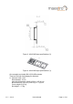
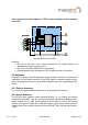
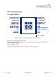
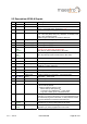
5.2 Description A2100-A Signals
Pin Symbol Function Description
1 nRST Input Reset input, active low
2 BOOTSEL Input Special boot mode – leave open for normal operation;
HIGH – boot loader active; HIGH level: 1.8V
3 Vcc Power Supply 3.0 – 3.6 VDC (power supply)
4 WAKEUP Output Status of digital section, Push-Pull output
Low = OFF, KA (Keep Alive)-only, Hibernate, or Standby mode
High = ON, operational mode
Identical logic to RFPWUP of A1084 on same pin!
5 Vout Voltage output Permanent 1.8V voltage output for up to 20mA current max.
6 GND Power Supply Ground (power supply)
7 GND Power Supply Ground (power supply)
8 GPIO6
CTS
SPI CLK
Input Configuration pin to run in UART mode (10k pull-up to 1.8V, e.g.
to Vout, pin 5), leave open for SPI mode.
SPI clock pin when module works in SPI mode
9 GPIO7
RTS
SPI CS
Input Unused configuration pin – reserved for future use, leave open
SPI chip select pin when module works in SPI mode
10 N.C. None Leave open
11 N.C. None Leave open
12 ANT Antenna Input Antenna signal / Z=50 Ohm (antenna input) – must not exceed
30dB gain including cable loss
13 ANT_GND RF GND Antenna Ground
14 N.C. None Leave open
15 VANT Antenna Supply
Voltage Input
Power supply input for external active antenna – provide ac-
cording voltage (up to 5.0 VDC) – switched internally
16 TM_GPIO5 Output Time Mark – 1PPS signal
17 I2C CLK Input I2C clock input for MEMS interface
18 I2C DIO Input/Output I2C I/O for MEMS interface
19 ON_OFF Input Connect to push-pull output! This is mandatory!
- Set to LOW by default
- Toggle to HIGH and back to LOW
- for first start-up after power on
- to request a fix in SiRFaware
TM
or PTF mode
- to go into or wake up out of hibernate mode
20 ExtInt Input Interrupt input for MEMS interface
(If ExtInt is not going to be used, it is recommended that this pin
be tied directly to ground. Otherwise, a 100K pull-down resistor
to ground should be connected to the ExtInt pin.)
21 TX0
SPI DO
Output Serial output 0, NMEA out if configured for UART
SPI data out pin when module works in SPI mode
22 RX0
SPI DI
Input Serial input 0, NMEA in if configured for UART
SPI data in pin when module works in SPI mode
Table 5: Pin description A2100-A