DIY Wireless Home Security System Installation Guide DIYSECURITY.CO.
Contents Introduction Part 1: Planning .................................................................................................................................................. 3 Part 2: Control Panel Installation ........................................................................................................................ 3 Part 3: Control Panel Programming....................................................................................................................
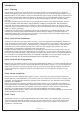
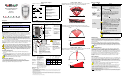
Introduction Part 1: Planning The first thing you’re going to want to do is figure out where you want to put the control panel. Typically, it’s easiest for everybody to place it by the door you use most frequently you can always add extra keypads to your Magellan system. You also need it to be near an electrical outlet (don’t choose one that’s switch-controlled).
System Planning Diagram Layout Diagram Example Mounting Guidelines DIYSECURITY.CO.
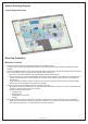
Figure 1 • • • The “dead spot”, or area where the RF signal is weak or non-existent, varies from one transmitter to the next • Mounting the receiver as central as possible to the transmitters will help in avoiding the “dead spots” Do not mount the transmitters too close to each other. Do not mount the transmitters too far or too close to the receiver.
PMD85 Outdoor 45Kg Pet Detector Installation Guide DIYSECURITY.CO.ZA 6 www.diysecurity.co.
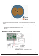
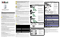
Figure / Figura / Figure 1 0* 30' 6(5,(6 B 723 9,(: R Step A P IW P IW P IW P IW DIP OFF Switch 2 ON 6,'( 9,(: MGPMD85-TI05 Figure / Figura / Figure 2 PCB Setup / Configuración de la PCI / Configuration de la carte de circuits imprimés The MG-PMD85 series features the following beam patterns: Beam Pattern MG-PMD85W Pet Array beam pattern (see figure 3) MG-PMD85L1 Horizontal Curtain beam pattern (see figure 4) MG-PMD85L2 Vertical Curtain beam pattern (see figure 5
Figure / Figura / Figure 1 0* 30' 6(5,(6 B 723 9,(: R Step A P IW P IW P IW P IW DIP OFF Switch 2 ON 6,'( 9,(: MGPMD85-TI05 Figure / Figura / Figure 2 PCB Setup / Configuración de la PCI / Configuration de la carte de circuits imprimés The MG-PMD85 series features the following beam patterns: Beam Pattern MG-PMD85W Pet Array beam pattern (see figure 3) MG-PMD85L1 Horizontal Curtain beam pattern (see figure 4) MG-PMD85L2 Vertical Curtain beam pattern (see figure 5
PMD75 45Kg Pet Detector Installation Guide DIYSECURITY.CO.ZA 7 www.diysecurity.co.
MGPMD75-TI00 Digital Wireless Motion Detector with Pet Immunity (MG-PMD75) V2.0 With an OMN-RCV3 V2.0 or higher, the receiver automatically detects the check-in time set in each of its assigned transmitters. As a result, the transmitters can have different check-in times. With a previous version of the OMN-RCV3, the transmitter check-in time needs to match the setting in the module.
MGPMD75-TI00 Digital Wireless Motion Detector with Pet Immunity (MG-PMD75) V2.0 With an OMN-RCV3 V2.0 or higher, the receiver automatically detects the check-in time set in each of its assigned transmitters. As a result, the transmitters can have different check-in times. With a previous version of the OMN-RCV3, the transmitter check-in time needs to match the setting in the module.
PMD1 18Kg Pet Detector Guide DIYSECURITY.CO.ZA 8 www.diysecurity.co.
J1 OFF = 12 minutes J1 ON = 12 hours (default) Analog Single-Optic PIR (18kg/40lbs Pet Immunity) (MG-PMD1P) V2.0 With an OMN-RCV3 V2.0 or higher, the receiver automatically detects the check-in time set in each of its assigned transmitters. As a result, the transmitters can have different check-in times. With a previous version of the OMN-RCV3, the transmitter check-in time needs to match the setting in the module. With an OMN-RCV3 V2.
J1 OFF = 12 minutes J1 ON = 12 hours (default) Analog Single-Optic PIR (18kg/40lbs Pet Immunity) (MG-PMD1P) V2.0 With an OMN-RCV3 V2.0 or higher, the receiver automatically detects the check-in time set in each of its assigned transmitters. As a result, the transmitters can have different check-in times. With a previous version of the OMN-RCV3, the transmitter check-in time needs to match the setting in the module. With an OMN-RCV3 V2.
Door Contact Installation Guide DIYSECURITY.CO.ZA 9 www.diysecurity.co.
JP2 JP1 Wireless 2-Zone Door Contact (Universal Transmitter) MG-DCTXP2 V3.0 Do not cut, bend or alter the antenna. Avoid mounting the door contact near or on metal as this may affect transmission. Learn Mode Learn Mode allows you to transmit the serial numbers of each input. To enter Learn Mode, open the cover and wait until the LED stops flashing. Anti-Tamper Switch Serial Number Visual Confirmation Press and release the anti-tamper switch once. SN = Reed switch (e.g.
DC Power Connect DIYSECURITY.CO.ZA 10 www.diysecurity.co.
• In extreme situations, the reflected RF wave (B) inverts and cancels out the direct path RF wave (A) • To remedy this, simply move the transmitter or receiver a few inches DIYSECURITY.CO.
Possible sources of electrical interference: • • • • • • • • • • TV or computer cathode ray tube (CRT) displays Electric welders Air conditioners continue on following page..... Brush-type motors Electrical Interference Relays and switches of all kinds Arcing and corona discharge in power line insulators Malfunctioning flourescent/neon lighting and automobile spark plugs Light dimmers Intermodulation • • • • • • • Occurs when a strong signal (i.e.
Refraction • Occurs when an RF wave crosses a boundary from one medium to another (i.e. from air to water). A wave entering a medium at an angle will change direction • Diffraction: It is the bending of RF waves around an object’s edge, such as a sharp corner or opening DIYSECURITY.CO.ZA • • • • • • • • • Objects that reflect and attenuate RF signals include: Metal objects Objects with metal in them Ground Circuit breaker boxes Trees: RF energy loss depends on the size and type of tree.
Contact Details Tel: 011 462 7610 Mobile: +27 (82) 903 7156 Email: info@diysecurity.co.za Website: www.diysecurity.co.za DIYSECURITY.CO.ZA 15 www.diysecurity.co.