
Installation guide

English
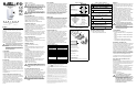
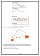
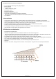
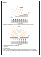
At the recommended installation height of 2.1m (7ft)
±10%, the MG-PMD1P will provide full coverage from
2m (6.5ft) to 15m (50ft), without any dead zones
(Figure 2).
Avoid placing the motion detector in proximity to
potential sources of interference such as: reflective
surfaces, direct air flow from vents, fans, windows,
sources of steam/oil vapor, and objects causing
temperature changes such as heaters, refrigerators,
ovens, and infrared light sources. Do not place objects
or furniture higher than 0.9m (3ft), which a pet can
climb onto (e.g. a cat on a couch), within 2.1m (7ft) of
the detector. In addition, do not aim the detector at a
stairway a pet may have access to.
Do not touch the sensor surface; this could result
in a motion detector malfunction. If necessary,
clean the sensor surface with pure alcohol using a
soft cloth.
Avoid bending, cutting or altering the antenna or
mounting the detector near or on metal as this may
affect signal transmission.
Compatibility
The MG-PMD1P is compatible with the following:
• Magellan All-In-One Wireless Console (MG-6060)
• Magellan Wireless Expansion Module (MG-RCV3)
• Omnia Wireless Expansion Module (OMN-RCV3)
• Spectra 1759EX control panel (Omnia protocol)
• Spectra 1759MG control panel (Magellan protocol)
Pet Immunity
An animal’s immunity to false alarms depends on its
size, temperature, and length of coat. Longer hair and
smaller size make an animal more likely to be immune,
while shorter hair and larger animals are more likely to
create a false alarm. When a higher level of immunity is
required, such as when animals are constantly in the
detection area, consider using our MG-PMD75 digital
dual-sensor high-performance PIR (40kg/90lbs true pet
immunity).
The MG-PMD1P pet immunity feature has not yet been
investigated by UL.
Check-in Supervision Time Value (J1)
Jumper J1 sets the time interval in which the detector
communicates a check-in signal when used with Omnia
or Spectra 1759EX (see Operating Mode).
If the detector is used with a Magellan receiver (see
Operating Mode), J1 is disabled and the detector will
regularly transmit a check-in signal to Magellan. The
check-in supervision time is set in the Magellan
receiver.
J1 OFF = 12 minutes
J1 ON = 12 hours (default)
With an OMN-RCV3 V2.0 or higher, the receiver
automatically detects the check-in time set in each
of its assigned transmitters. As a result, the
transmitters can have different check-in times. With
a previous version of the OMN-RCV3, the
transmitter check-in time needs to match the
setting in the module.
With an OMN-RCV3 V2.0 or higher, if the check-in
time setting is changed, power down and then
power up the receiver in order for the change to be
recognized.
Operating Mode (J2)
MG-PMD1P can function on either the Magellan or
Omnia communication protocol. Set J2 according to
which receiver the MG-PMD1P will communicate with.
J2 OFF = Omnia / Spectra 1759EX
J2 ON = Magellan / Spectra 1759MG (default)
Sensitivity Setting (J3)
J3 OFF = (High Sensitivity) In "1-3 mode", you should
not be able to cross more than one complete zone
(consisting of two beams - left and right sensor
detecting elements) in the coverage area with any kind
of movement. Use this setting for the majority of
installations (default).
J3 ON = (Low Sensitivity) In "2-6 mode", the amount of
movement required to generate an alarm is doubled.
The use of 2-6 mode is recommended in areas where
the incidence of false alarms may be greater.
Fast / Slow Mode (J4)
J4 OFF =
"Slow Mode" is suggested in areas where the
incidence of false alarms may be greater.
J4 ON = "Fast Mode" is recommended for the majority
of installations (default).
LED ON / OFF (J5)
The red LED indicates the following:
Alarm
The red LED will illuminate for a period of 2 seconds
whenever the motion detector detects any kind of
movement.
Low Battery
The motion detector performs a battery test every 12
hours. If the battery voltage drops below a certain level,
the red LED will flash at 5-second intervals and the
motion detector will send a low battery signal to the
receiver. A trouble will be generated and then
transmitted to the central monitoring station.
Signal Transmission
The red LED indicator light will blink rapidly when the
motion detector transmits a signal to the receiver.
J5 OFF = LED deactivated
J5 ON = LED activated (default)
After changing the jumper settings, replace the
cover to close the anti-tamper switch, or press and
release the anti-tamper switch, in order to save the
changes.
Powering the Wireless Detector
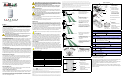
Verifying proper polarity, insert three “AA” alkaline
batteries into the motion detector’s battery
compartment. To replace the batteries, remove the old
batteries, then press and release the anti-tamper switch
and wait 60 seconds in order to reinitialize the unit.
Insert new batteries while verifying proper polarity.
After inserting the batteries in the motion detector,
a power-up sequence will begin (lasting 10-30
seconds). During this time, the red LED will flash
and the detector will not detect an open zone or
tamper.
Alive Software
To conserve the motion detector’s battery life, if the motion
detector transmits 2 open zone signals (LED on for 2 s)
within a 5-minute period, the detector will fall into Energy
Save Mode where it will not transmit any alarm signals for
approximately 3 minutes. Due to the motion detector’s
Alive Software, the red LED will continue to flash to indicate
a detection even when in Energy Save Mode. Once the
three-minute Energy Save Mode ends, the motion detector
returns to normal operation. If the detector’s cover is
removed and then replaced while in Energy Save Mode,
the first detection will trigger an alarm signal.
Walk-testing
Open the cover in order to trigger the anti-tamper switch,
then snap the cover back into position. This will activate
the motion detector’s walk-test mode for 3 minutes. In
“fast” mode (J4 = ON), at 20°C, you should not be able
to cross more than one complete zone (consisting of two
beams left and right sensor detecting elements) in the
coverage area with any kind of movement; slow/fast
walking or running. In slow mode (J4 = OFF), the
amount of movement required to generate an alarm is
doubled. Walk-test mode is also activated for 3 minutes
once the motion detector is powered on.
Signal Strength Test
In order to verify the receiver's reception of the motion
detector’s signal, perform a signal strength test as
described in the receiver’s Reference and Installation
Manual before finalizing the installation of the motion
detector. Prior to performing the test, make sure the
batteries have been inserted into the battery
compartment to power the detector. Also verify that the
motion detector has been assigned to a zone according
to the instructions in the receiver’s Reference and
Installation Manual. If the transmission is weak,
relocating the transmitter by a few inches can greatly
improve the reception.
* FCC ID: KDYOMNPMD1 IC: 2438A-104560
The MG-PMD1P complies with part 15 of the FCC rules. Operation is subject to the following two
conditions: (1) This device may not cause harmful interference, and (2) This device must accept any
interference received, including interference that may cause undesired operation.
** 868MHz (only) compliant to all EU and EFTA countries except Greece according to
RTT&E directives. Please note that the 868MHz version is not UL approved.
†
Battery life expectancy will vary according to the check-in time interval and the amount of traffic
(movement) the detector has processed. A higher check-in time interval and higher traffic will lower
battery life.
Warranty
Paradox Security Systems Ltd. (“Seller”) warrants its products to be free from defects in materials and
workmanship under normal use for a period of one year. Except as specifically stated herein, all express or
implied warranties whatsoever, statutory or otherwise, including without limitation, any implied warranty of
merchantability and fitness for a particular purpose, are expressly excluded. Because Seller does not install or
connect the products and because the products may be used in conjunction with products not manufactured
by Seller, Seller cannot guarantee the performance of the security system and shall not be responsible for
circumstances resulting from the product’s inability to operate. Seller obligation and liability under this warranty
is expressly limited to repairing or replacing, at Seller's option, any product not meeting the specifications.
Returns must include proof of purchase and be within the warranty period. In no event shall the Seller be liable
to the buyer or any other person for any loss or damages whether direct or indirect or consequential or
incidental, including without limitation, any damages for lost profits stolen goods, or claims by any other party,
caused by defective goods or otherwise arising from the improper, incorrect or otherwise faulty installation or
use of the merchandise sold.
Notwithstanding the preceding paragraph, the Seller’s maximum liability will be strictly limited to the purchase
price of the defective product. Your use of this product signifies your acceptance of this warranty.
BEWARE: Dealers, installers and/or others selling the product are not authorized to modify this warranty
or make additional warranties that are binding on the Seller.
Note: The warranty does not apply to the alkaline batteries provided with the unit.
One of the following US patents may apply: 6215399, 6111256, 6104319, 5920259, 5886632, 5751803,
5721542, 5287111, 5119069 and 5077549. Canadian and international patents may also apply. LODIFF®
registered trademark of Fresnel Technologies Inc. Omnia, Magellan and Spectra are trademarks or
registered trademarks of Paradox Security Systems Ltd. and its affiliates in Canada, the United States and
other countries. All rights reserved. Specifications may change without prior notice.
© 2002-2005 Paradox Security Systems Ltd.
Figure 1 / Figura 1
Figure 2 / Figura 2
Figure 3 / Figura 3
Table 1 / Tabla 1 / Tableau 1
U= default / de fábrica / par défaut;
* = Omnia / Spectra 1759EX only;
* = Sólo Omnia / Spectra 1759EX;
* = Omnia / Spectra 1759EX seulement
Español
Instalado a la altura recomendada de 2.1m (7ft) ±10%,
el MG-PMD1P brinda una cobertura total desde 2m
(6.5 ft) hasta 15m (50ft) sin niguna zona ciega (ver la
Figura 2).
Evitar ubicar el detector de movimiento cerca de
fuentes potenciales de interferencia como: superficies
reflectantes, corrientes de aire provenientes de
sistemas de ventilación, ventiladores, ventanas,
fuentes de vapor de agua / humo de aceite, y objetos
que provoquen cambios de temperatura como
aparatos de calefacción, refrigeradores, hornos y
fuentes de luces infrarrojas. No poner objetos o
muebles de más de 0.9m (3ft) de altura, sobre los
cuales pueda trepar una mascota (i.e. un gato sobre un
sofá), a 2.1m (7ft) o menos del detector. Además, no
dirigir el detector hacia una escalera por donde pueda
entrar una mascota.
No tocar la superficie del sensor pues puede
provocar un mal funcionamiento del detector. De
ser necesario, limpiar la superficie del sensor con
un paño delicado y alcohol puro.
Evitar doblar, cortar o alterar la antena o montar el
detector cerca de o sobre metal pues esto puede
afectar la transmisión de la señal.
Compatibilidad
El MG-PMD1P es compatible con:
• Consola Inalámbrica Todo en Uno Magellan (MG-
6060)
• Módulo de Expansión Inalámbrico Magellan (MG-
RCV3)
• Módulo de Expansión Inalámbrico Omnia (OMN-
RCV3)
• Central Spectra 1759EX (protocolo Omnia)
• Central Spectra 1759MG (protocolo Magellan)
Inmunidad contra Mascotas
El que un animal no genere falsas alarmas depende de
su tamaño, temperatura, y del largo de su pelaje. El
pelo largo y el tamaño pequeño disminuyen la
generación de falsas alarmas, mientras que un animal
de pelo corto y gran tamaño tiene más posibilidades de
crear una falsa alarma. Para los casos en que sea
necesario un nivel de inmunidad superior, p.e.
animales que caminan constantemente en el área de
detección, considere usar nuestro doble sensor digital
de alto rendimiento MG-PMD75 (con inmunidad real
contra mascotas de hasta 40kg/90lbs de peso).
La característica de inmunidad contra mascotas del
MG-PMD1P aún no ha sido inspeccionada por UL.
Valor del Tiempo de Verificación de
Presencia (J1)
El Puente J1 establece el intervalo de tiempo en el cual
el detector transmitirá una señal de presencia cuando
se usa con Omnia o Spectra 1759EX (ver Modo de
Funcionamiento).
Si el detector es usado con un receptor Magellan (ver
Modo de Funcionamiento), el puente J1 es
deshabilitado y el detector transmitirá regularmente
una señal de presencia a Magellan. El tiempo de
verificación de presencia es definido en el receptor
Magellan.
J1 OFF = 12 minutos
J1 ON = 12 horas (de fábrica)
Con un OMN-RCV3 o posterior, el receptor
detecta automáticamente el tiempo de
supervisión de presencia definido en cada uno
de sus transmisores asignados. Por lo tanto, los
transmisores pueden tener tiempos de
verificación distintos. En una versión anterior
del OMN-RCV3, el tiempo de verificación de
presencia del transmisor debe coincidir con el
tiempo definido en el módulo.
Analog Single-Optic PIR
(18kg/40lbs Pet Immunity)
(MG-PMD1P)
V2.0
Instructions
Instrucciones
780 Industriel Blvd., Saint-Eustache (Quebec) J7R 5V3 CANADA
Tel.: (450) 491-7444 Fax: (450) 491-2313
www.paradox.ca
PRINTED IN CANADA - 06/2005 MGPMD1P-TI03
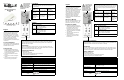
Technical Specifications
Sensor Type Dual rectangular element
Coverage - 88.5° (standard) 11m x 11m (35ft x 35ft)
Center beams: 15m (50ft)
Installation Height 2.1m to 2.7m (7ft to 9ft)
Pet Immunity 18kg (40lbs)
Operating Temp. 0°C to 49°C (32°F to 120°F)
RF Frequency 433* or 868** MHz
Lens 2nd generation Fresnel lens,
LODIFF®, Pet Immune
Power 3 x “AA” Alkaline batteries
Transmitter Range 35m (115ft) with MG-6060; 70m
(230ft) with MG-RCV3; in a
typical residential environment
Anti-Tamper Switch Yes
Battery Life
†
Up to 4 years
UL approved detection speed 0.76m/s (30 in/s)
A
Corner Mount
Montaje en esquina
Montage en coin
B
Flat Surface Mount
Montaje en superficie plana
Montage sur surface plane
A
B
A
A
A
B
B
B
11m x 11m
(35ft x 35ft)
Center beams:
15m (50ft)
11m x 11m
(35ft x 35ft)
Haces centrales:
15m (50ft)
11 m x 11 m
(35 pi x 35 pi)
faisceaux du centre :
15 m (50 pi)
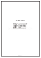
A
- Anti-tamper Switch
- Interruptor antisabotaje
- Interrupteur de sécurité
B
- Antenna / Antena / Antenne
C
- Battery Compartment
- Compartimiento de bateria
- Compartiment à piles
D
- LED / LED / DEL
E
- Sensor / Sensor / Capteur
F
- PCB height markings
- Marcas de altura de PCI
- Marques pour hauteur de la carte de circuits imprimés
A
B
C
D
E
F
J1
J3
J4
J5
C
J2
LED Indicator / Indicador LED / Voyant DEL
J5
OFF = Disabled / deshabilitado / désactivé
ON = Enabled / habilitado / activé U
Fast - Slow Mode / Modo Rápido - Lento /
Mode rapide - lent
J4
OFF = Slow Mode / Mode Lento / Mode lent
ON = Fast Mode / Modo rápido / Mode rapide U
Sensitivity Setting / Configuración de la
Sensibilidad / Réglage de la sensibilité
J3
OFF = High Sensitivity / Alta Sensibilidad /
Sensibilité élevée
ON = Low Sensitivity / Sensibilidad Lenta /
Sensibilité faible U
Operating Mode / Modo de funcionamiento /
Mode de fonctionnement
J2
OFF = Omnia / Spectra 1759EX
ON = Magellan / Spectra 1759MGU
Check-in Supervision Timer /
Tiempo de Verificación de Prescencia /
Délai de supervision de présence
J1*
OFF = 12 minutes / minutos / minutes
ON = 12 hours / horas / heures U
DIYSECURITY.CO.ZA