All-In-One Wireless Security System V1.
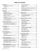
Table of Contents Introduction................................................... 3 About Magellan and this Manual............................. 3 Conventions ............................................................ 3 Specifications.......................................................... 3 Quick Setup................................................... 4 Installation..................................................... 6 AC Power................................................................
Panel Answer Options ........................................... 33 Panel Identifier....................................................... 33 PC Password ......................................................... 33 PC Telephone Number .......................................... 33 Call Back Feature .................................................. 33 Appendix 1: Ademco Contact ID Report Code List ............................................................... 34 Index .....................................
Introduction About Magellan and this Manual Specifications Magellan is designed for fast and easy installation. Simply remove it from the box, mount the console and wireless transmitters, apply power and Magellan is ready to protect your home. Magellan has already been pre-programmed with the required settings for a basic security installation. Power input: Some of Magellan’s features can be programmed through a quick Installer Menu (menu programming) or through section programming.
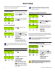
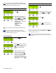
Quick Setup Follow these steps to quickly set up Magellan with the required settings for a basic security installation. For more in-depth programming of the console’s communication features, see Reporting and Dialer Settings on page 24. 1.Getting Started 1. After powering up for the first time, press [START] to access the Installer Menu. 2. The first menu option will appear. Press [NEXT] to go to the “User Profile” menu. 2.User Programming 1. From the “User Profile” menu, press [OK]. 2.
When you are done the next menu option will appear. Press [NEXT] until you see the “Passwords” menu or press the [8] key to immediately access the “Passwords” menu. Deleting Zones 1. From the “Zone Profile” menu, press [OK]. 6.Passwords 1. From the “Passwords” menu, press [OK]. 2. Select which password(s) or code(s) you wish to program by pressing [NEXT] and press [OK] when the desired password appears.
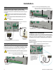
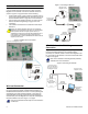
Installation Figure 2: Connecting the Backup Battery (cont’d) AC Power Magellan requires a 9Vac (1A/9VA) or 16.5Vac (20VA) transformer (not included) to supply power to the console. Connect the transformer to the AC terminals as shown in Figure 1 on page 6. 2. Slide in the battery pack horizontally, tilt the battery pack downward and then tuck it in Magellan’s battery compartment. Magellan can also be powered through a DC power supply. Connect a 12Vdc to 18Vdc to the AC terminals to power the console.
For UL compliant installations, the Magellan console must be able to seize the telephone line and place a call in an emergency situation. It must be able to do this even if other equipment (telephones, answering machines, computer modems, etc.) already has the line in use. To do so, the Magellan console must be connected to a properly installed RJ31X jack that is electronically in series with and ahead of all other equipment attached to the same telephone line.
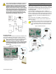
Figure 7: Connecting to WInLoad Hardwire Zone Connections Back view of the Magellan console. Magellan comes with two on-board hardwire zones. You can connect hardwire detection devices such as door contacts to Magellan’s zone terminals. Connect the detection devices as shown in Figure 6 on page 8. Please note the following: • Section [095] options [1] and [2] must be enabled in order to use the two on-board hardwire zones. See Zones 15 and 16 become Hardwire Zones on page 16 for more information.
X10 Transmitter Connection Location and Mounting Magellan supports the X10 communication protocol. X10 is a communication protocol for remote control of electrical devices such as lamps and appliances. Communication is accomplished through standard household electrical wiring using X10 transmitters and receivers. Configure Magellan, with the use of an X10 transmitter, to automate a home. Connect the X10 transmitter as shown in Figure 9 on page 9. Refer to the Magellan X10 Instructions on our website, www.
Figure 12: Mounting Magellan onto the Wall Plate rubber stops prevent the console from sliding when Magellan is being used. To do so: 1. Place the console back plate flush against the wall plate. 2. Slide the Magellan’s open slots labeled D (see Figure 13 on page 10) onto the wall plate’s tabs labeled B (see Figure 12 on page 10). 3. Gently apply downward pressure to insert the wall plate’s tabs into Magellan’s open slots. 4.
Programming Methods WinLoad Installer Upload/Download Software Program the Magellan console remotely or on-site using the WinLoad Installer Upload/Download Software for Windows®. For more information, contact your local Paradox Distributor or visit our Web site at www.paradox.ca. If you are using the WinLoad software, you must program the features explained on page 33. Please refer to WinLoad’s Online Help for more information on using WinLoad.
User Codes A person must be assigned to a user code in order to have access to Magellan. A user code defines the extent of a user’s access to the system and consists of a code # (PIN) and user options. Magellan supports one Installer code, one Maintenance code and up to 16 user codes (one System Master code and 15 User codes).
Zone Programming Magellan supports up to 16 wireless zones where each zone can be configured with a different zone definition and option. Each zone can also have a voice label recorded for it. Magellan’s zones can be programmed using section programming or through the Installer menu. See Quick Setup on page 4 for more information on zone programming using the Installer menu.
Follow/Stay Zones Figure 18: Delayed Fire Zone Sections [001] to [016]: Zones 1 to 16, 3-digit # = 004 Follow/Stay zones function as follows: • • All zones defined as Follow/Stay zones become Follow zones (refer to Follow Zones on page 13) when the Magellan system is Regular armed. All zones defined as Follow/Stay zones become Stay zones when the Magellan system is Stay or Instant armed.
24Hr. Gas Zones Sections [001] to [016]: Zones 1 to 16, 3-digit # = 012 When a 24Hr. Gas zone opens, whether it is armed or disarmed, the console will immediately generate an alarm. The SIA FSK reporting format includes specific report codes to identify the alarm as a Gas alarm. When a user uses the Bypass Programming feature, only zones with the Bypass option enabled can be programmed as bypassed. Fire zones cannot be programmed with the Bypass option because the console will not bypass a Fire zone.
Intellizone Delay Timer Section [065]: 010 to 255 seconds; Default = 48 seconds Enter the desired 3-digit value into section [065] to program the Intellizone Delay Timer. Delay Before Alarm Report Code Transmission follows the Entry Delay 2 Timer of its assigned partition. To program the Entry Delay Timers, refer to Entry Delay 1 and Entry Delay 2 on page 13.
Wireless Programming The Magellan system supports up to 16 wireless zones and two wireless doorbells. These wireless zones are monitored using transmitters such as wireless detectors and door contacts. The Magellan console only supports the Paradox Magellan series of wireless transmitters. The programming of the transmitters is accomplished in two steps: 1. Assign the wireless transmitter to Magellan. 2. Program the wireless zone.
The signal strength is displayed using two terms: • • “Good”: This is an average reading and is acceptable. “Weak”: This is the weakest reading. The transmitter should be moved to another location. Sometimes moving the transmitter by a small amount will greatly increase the signal reception. To view the signal strength of a wireless transmitter: 1. Access the installer programming mode (page 11). 2. Enter the [SECTION] corresponding to the desired zone or doorbell. 3.
Figure 20: Remote Control Button Options Hexa Value Description Hexa Value Description 0 Button disabled 8 Panic 1† 1 Regular arming 9 Panic 2† 2 Stay arming A* Panic 3† 3 Instant arming B* PGM Activation (Event Group #07 - Refer to the Magellan Programming Guide) 4 Force arming C* PGM Activation (Event Group #08 - Refer to the Magellan Programming Guide) 5 Future use D* Turn FM radio ON/OFF 6 Future use E* FM radio memory scan 7 Future use F* Paramedic alarm * = Hexa val
Arming and Disarming Regular Arming Switches to Stay Arming Section [092]: Option [4] Option [4] OFF = Switch to Stay arming disabled (default) Option [4] ON = Switch to Stay arming enabled If a user Regular arms the system, but does not exit through (open and close) an Entry Delay zone during the Exit Delay, the console can be programmed to switch from Regular arming to Stay arming. Regular Arming Switches to Force Arming Auto-arm Timer Section [085] Program the time (use the 24-hour clock i.e.
One-Touch Arming Follow Zone Switches to Entry Delay 2 Section [092]: Options [7] and [8] Option [7] OFF = One-touch Regular/Force arming disabled Option [7] ON = One-touch Regular/Force arming enabled (default) Section [093]: Option [7] Option [7] OFF = Follow zone triggers an alarm (default) Option [7] ON = Follow zone follows Entry delay 2 when opened Option [8] OFF = One-touch Stay arming disabled Option [8] ON = One-touch Stay arming enabled (default) When option [7] is enabled (ON) and an Entry D
Alarm Options Bell Cut-off Timer Tamper Recognition Options Section [063]: 001 to 255 minutes; 000 = Disabled; Default = 4 minutes Section [094]: Options [3] and [4] After an audible alarm, the siren will stop upon disarming of the system or when the Bell Cut-Off timer has elapsed, whichever comes first. This feature determines how the Magellan console will react to a zone tamper. Table 6 shows the different tamper recognition combinations available and how the system will react when armed or disarmed.
presence and functionality. If a device has not sent a signal within the specified time period, Magellan can generate a trouble, an alarm and/or transmit a report code to the central monitoring station as defined by the Wireless Transmitter Supervision Options (page 22). Sections [103] and [104] determine which zones will be supervised and which will not. Enable the option pertaining to the zone you wish Magellan to supervise.
Reporting and Dialer Settings Report Codes A report code is a 1- or 2-digit hexadecimal value consisting of digits from 1 to F. Each section from [120] to [156] represents a set of up to four specific events and each of these events can be programmed with a separate 1- or 2-digit report code. Only the Ademco Slow, Silent Knight, and Sescoa formats support 1-digit report codes. To program a 1-digit report code, press the [0] key followed by the desired hexadecimal digit or vice versa.
• • • Auxiliary Panic: Panic keys [4] and [6] (page 23) or the appropriate button(s) on a remote control (page 18) have been pressed. Fire Panic: Panic keys [7] and [9] (page 23) or the appropriate button(s) on a remote control (page 18) have been pressed. Recent Closing: Reports when an alarm is generated after arming the system within period defined by the Recent Close Delay (see page 28).
section [114]. If the message is less than 32 digits, press the left [ACTION] key (ok) to save the message. Table 8: Special Keys for Telephone Numbers Keys to press Action or Value [*] * [#] # Center [ACTION] (pause) key Add a 4-second pause to the telephone number.
[0] key followed by the 3-digit account number. Also, when using 3-digit account numbers, you must use 1-digit report codes.
Delay Between Dialing Attempts Section [076]: 001 to 255 seconds; 000 = disabled; Default = 20 seconds communication. When the console switches to another CSTN, it returns to tone/DTMF dialing and will once again switch to pulse dialing on the fifth attempt. This delay determines the amount of time the Magellan console will wait between each dialing attempt.
Auto-Test Report Section [071]: 001 to 255 days; 000 = Disabled; Default = Disabled Section [084]: Time (HH:MM) The Magellan console will transmit the Test Report report code programmed into section [153] after the number of days programmed into section [071] has elapsed at the time programmed into section [084]. Use the 24-hour clock to program the time (i.e. 6:30PM = 18:30). The first Test Report will be transmitted within 24 hours after the feature is enabled at the time programmed in [084].
Programmable Outputs A PGM is a programmable output that toggles to its opposite state (i.e. a normally open PGM will close) when a specific event has occurred in the system. For example, a PGM can be used to activate bells or strobe lights, open/close garage doors and much more. When a PGM closes, the control panel supplies a ground to the PGM activating any device or relay connected to it. When a PGM opens, the circuit opens from ground, therefore, cutting power to any devices connected to it.
System Settings Software Reset Daylight Savings Time Section [201] Section [096]: Option [5] Option [5] OFF = Daylight savings time disabled (default) Option [5] ON = Daylight savings time enabled Performing a software reset will reset all programmed sections back to the factory defaults. To perform a software reset: 1. 2. Access the installer programming mode (page 11). Enter section [201].
Trouble Description AC Failure Power failure detected. The system is running on the backup battery pack. Supervision Trouble Zone(s) displayed have not sent a check-in signal within the programmed interval (page 22). Console Tamper The Magellan console was tampered with. Zone Tamper Zones displayed were tampered with. Fail to Communicate with Central The Magellan console has failed to contact the monitoring station.
WinLoad Software Settings Panel Answer Options The following two options define how Magellan answers an incoming call from a computer using the WinLoad Installer Upload/Download Software. Answering Machine Override Section [074]: 010 to 255 seconds; 000 = disabled; Default = disabled When using WinLoad to communicate remotely with an installation site that uses an answering machine or service, the answering machine override must be programmed. Using WinLoad, you will call Magellan, hang up, then call back.
Appendix 1: Ademco Contact ID Report Code List CID# Reporting Code Programming Value Medical Alarms - 100 100 Medical alarm 01 101 Pendant transmitter 02 102 Fail to report in 03 Fire Alarms - 110 Reporting Code Programming Value 154 Water leakage 29 155 Foil break 2A 156 Day trouble 2B 157 Low bottled gas level 2C 158 High temperature 2D 159 Low temperature 2E 110 Fire alarm 04 161 Loss of air flow 2F 111 Smoke 05 162 Carbon monoxide detected 30 112 Combustion
CID# Reporting Code Programming Value 335 Local printer paper out 54 336 Local printer failure 55 337 Expansion module DC loss 56 338 Expansion module low battery 57 339 Expansion module reset 58 341 Expansion module tamper 59 342 Expansion module AC loss 5A 343 Expansion module self-test fail 5B 344 RF receiver jam detect 5C Communication Troubles - 350 and 360 CID# Reporting Code Programming Value 408 Quick arm 81 409 Keyswitch open/close 82 Remote Access - 410 411
CID# Reporting Code Programming Value 525 Reversing relay disabled AE 526 Notification appliance chk. #3 disabled AF 527 Notification appliance chk. #4 disabled B0 Modules - 530 531 Module added B1 532 Module removed B2 Communication Disables - 550 and 560 551 Dialer disabled B3 552 Radio transmitter disabled B4 Bypasses - 570 570 Zone bypass B5 571 Fire bypass B6 572 24Hr.
Index Numerics 001 to 016 .............................................................. 13–16 021 to 036 .....................................................................17 041 to 056 .....................................................................18 058 ................................................................................17 059 ................................................................................17 060 ........................................................................
Answering machine override .........................................33 Arming options Auto-arm options .......................................................20 Bell Squawk on Arm/Disarm with Remote Control .........21 Closing Delinquency Timer .........................................21 Exit delay ..................................................................21 Exit Delay Termination ...............................................21 Follow Zone switches to Entry Delay 2 .........................
E O Entry Delay 1 .................................................................13 Entry Delay 2 .................................................................13 EOL zones .....................................................................16 Event PGM activation ..........................................................30 PGM deactivation ......................................................30 Event call direction ........................................................27 Exit Delay Termination .
Special disarming ......................................................24 System trouble ..........................................................25 System trouble restore ...............................................25 Test .........................................................................29 Zone alarm ...............................................................24 Zone alarm restore ....................................................24 Zone tamper ............................................
V Viewing ..........................................................................17 Viewing transmitter signal strength ...............................17 Voice message repetitions ............................................26 Voice message telephone numbers ..............................26 Zone tamper restore report codes ................................ 25 Zone, hardwire ................................................................ 8 W Wall plate ...................................................
42 Reference & Installation Manual
WARRANTY Paradox Security Systems Ltd. (“Seller”) warrants its products to be free from defects in materials and workmanship under normal use for a period of one year. Except as specifically stated herein, all express or implied warranties whatsoever, statutory or otherwise, including without limitation, any implied warranty of merchantability and fitness for a particular purpose, are expressly excluded.
780 Industriel Blvd., Saint-Eustache (Quebec) J7R 5V3 CANADA Tel.: (450) 491-7444 Fax: (450) 491-7313 www.paradox.