Magellan GPS Satellite Navigator User Manual Meridian XL
WARNINGS USE GOOD JUDGEMENT This product is an excellent navigation aid, but does not replace the need for careful orienteering and good judgement. Never rely solely on one device for navigating. USE CARE The Global Positioning System (GPS) is operated by the U.S. Government, which is solely responsible for the accuracy and maintenance of GPS. The accuracy of position fixes can be affected by the periodic adjustments to GPS satellites made by the U.S.
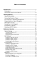
Table of Contents Introduction ........................................................................ 1 Packing List ................................................................................ 1 Conventions Used In This Manual ............................................. 2 Getting Started ................................................................... 3 General Description ................................................................... 3 Connecting Receiver Power ..........................
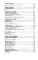
Viewing a Waypoint ......................................................................... 27 Accessing the Waypoint Function Menu .......................................... 28 Projecting a Waypoint ...................................................................... 28 Editing a Waypoint ........................................................................... 29 Deleting a Waypoint ......................................................................... 30 Routes ..................................
Power Lock ...................................................................................... 47 Light Intensity .................................................................................. 48 Contrast ........................................................................................... 48 Additional Features .................................................................. 48 Viewing the SAT STATUS Screen ................................................... 48 Viewing the Odometer ........
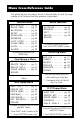
Menu Cross-Reference Guide This guide displays the menus found in the Meridian XL and the page number of this manual that the operation is described. Function Menu SAT STATUS .... pg. 48 ROUTE MENU .... pg. 31 WAYPOINTS ..... pg. 24 SETUP ......... pg. 42 SIMULATOR ..... pg. 51 ODOMETER ...... pg. 48 LAST FIXES .... pg. 41 CLEAR MENU .... pg. 51 CLOCK ......... pg. 49 ALARMS ........ pg. 49 Accessed by pressing the MENU key. Clear Memory Menu DELETE LFIXES . pg. 51 DELETE TRACK .. pg. 51 DELETE WPTS ...
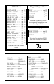
SETUP Menu INITIALIZE .... COORD SYSTEM .. ELEV MODE ..... TIME FORMAT ... VELOCITY AVG .. SPEED UNITS ... DIST UNITS .... ELEV UNITS .... NORTH REF ..... MAP DATUM ..... NMEA .......... BAUD RATE ..... WPT SORT ...... LFIX INTERVAL . PLOT SETUP .... SAMPLING ...... POWER LOCK .... LIGHT INTEN ... CONTRAST ...... Waypoint Popup Menu pg. 42 pg. 43 pg. 43 pg. 44 pg. 44 pg. 44 pg. 45 pg. 45 pg. 45 pg. 45 pg. 45 pg. 46 pg. 46 pg. 46 pg. 46 pg. 47 pg. 47 pg. 48 pg. 48 EDIT .......... WPT PROJEC .... SUNRISE ..
Welcome from the Magellan crew. With the purchase of a Magellan GPS satellite receiver, you have joined the thousands of people who enjoy using GPS in their professional and recreational activities. Since we introduced our first product more than five years ago, Magellan has established a reputation for product excellence and customer support. Our customers include sailors, commercial fishermen, pilots, geologists, explorers, surveyors, and the Allied Forces in Desert Storm.
Introduction Your Magellan GPS receiver has the advanced navigation features that experienced navigators expect, yet is simple enough for the novice navigator. This manual is broken up into four chapters; Introduction, Getting Started, Reference, and Appendix. It is very important that you go through the Getting Started chapter first as it prepares your receiver for use and provides some basic instruction for getting you up and running with your GPS receiver.
Conventions Used In This Manual WARNING: Warning messages will occur to alert you to potential problems that may be encountered if you do not follow the directions carefully. NOTE: Note messages are shown to provide important information that will assist you in understanding your Magellan receiver and its operation. If you are following along with your receiver during the step-by-step instructions, you should make key presses whenever the key name is in bold text.
Getting Started General Description The Meridian XL is a self-contained hand-held GPS receiver designed for general purpose position locating and navigation. It has a removable quadrifilar antenna located on the upper right side of the receiver, a highcontrast backlit LCD, and keypad. Using three AA batteries, inserted from the battery door found behind and near the base of the receiver, the Meridian XL will operate continuously for up to 6 hours.
Receiver Accuracy. Before beginning, just a few words on the accuracy of your receiver. The satellite constellation used to provide the GPS information that your receiver uses was put into orbit and is maintained by the Department of Defense (DoD) for use by the U.S. armed forces and its allies. GPS positioning for general use produces an accuracy of 25 meters or better, far more accurate than anyone anticipated.
First Time Use - Initializing the Receiver You do not need to initialize your receiver each time you use it. Follow these steps to initialize the Meridian XL if this is the first time you are using it, if the receiver memory has been cleared or if the receiver has been transported more than 300 miles while turned off. In the latter case, you are not automatically prompted by the receiver to reinitialize and the POSITION screen is displayed instead of the initialization warning after the start-up screens.
If you inadvertently press another key without initializing manually, the receiver displays the POSITION screen with null values for the latitude and longitude (00°00.00N, 000°00.00W). In this case, the receiver will self-initialize, which may take 15 minutes or more. The elevation mode will automatically switch from 2D to 3D, which is necessary to obtain a proper first fix. The recommended method is to press ENTER and initialize manually, which will allow the receiver to get a position fix sooner.
If this is not the first time you have used your receiver, or if it is the first time but your receiver has already begun acquiring satellite signals, the following time and date entry may not be displayed. Input your local time. Take extra care to input the time correctly (to within 10 minutes), including the AM/PM designator. Use the ARROW KEYs to change the time. Use the UP/DOWN ARROWs to change “AM” to “PM” if necessary. When the time is correct, press ENTER. TIME 37`00.00N 119`00.
Press the UP ARROW. Notice that the highlighted number has incremented by one. Keep pressing the UP ARROW until the first digit matches the first number you found for latitude. If you go past the number you want, you can use the DOWN ARROW to step down or continue using the UP ARROW and loop through the number sequence. When the correct number is displayed, press the RIGHT ARROW to step to the second digit on the latitude line.
The receiver will prompt you for your local elevation, time and date. Use the UP/DOWN and RIGHT/ LEFT ARROWs to enter these as described above; press ENTER to confirm each screen. COORDINATE 34`17.00N 118`39.00W +00000FT EL COORDINATE 34`17.00N 118`39.00W +00000FT EL 05:19PM The receiver is now ready to perform one of its primary functions, providing you with your current position.
Taking your First Fix To get a position fix, you must be outside with a clear view of the sky and away from any large obstructions (buildings, large trees, etc.). Rotate the antenna upward and hold the receiver in a comfortable position. If the receiver is off, press the POWER key to turn the receiver on, or if you have just finished initializing the receiver, press the NAV key until the screen showing your coordinates is displayed. This screen is called the POSITION screen.
Press NAV or PLOT (which will take you to a NAV or PLOT screen if you are not already there), then press ENTER, highlight SAVE POS and press ENTER. This tells the receiver that you want to store the current position as a waypoint. The cursor is in the upper left corner, and the arrows displayed in the lower right corner of the screen indicate that it is in the edit mode. What you will do next is assign a name to this position. SAVE POS 34`06.58N 117`49.
Selecting CREATE WPT instead of SAVE POS will allow you to enter a waypoint exactly as described above with the additional option of changing the latitude, longitude, and elevation of the position. (See Creating Waypoints) Press the RIGHT ARROW. This moves the cursor one space to the right. Select the letter “D” by using the UP/DOWN ARROWs. Press the RIGHT ARROW moving the cursor again one character to the right. Select the letter “O” by using the UP/ DOWN ARROWs. SAVE POS D 34`06.58N 117`49.
Introduction to Routes A route is a planned course of travel defined by a series of waypoints. To create a route, you select waypoints that you have stored in the receiver’s memory. These waypoints are then connected to form the segments or “legs” of the route. A route may contain from one to fifteen legs. Suppose you were on a fishing trip in the area shown below. You want to go from the dock to the bait shop, then across to the inlet on the island.
If the receiver has not yet computed a position fix, then the start of the GOTO may not represent your current position. It will, however, correct the navigation information after a position fix is acquired. Creating a GOTO Route After computing a position fix, press GOTO. Use the UP/DOWN ARROWs to highlight the waypoint that represents your destination.
Reference Section This section explains the various functions of your receiver and is organized by function or topic rather than by menu. To perform a given function, refer to the Table of Contents and the Menu Cross Reference Guide in order to quickly locate that section. General Usage The receiver is used to compute coordinate positions which are stored as named waypoints and used to create routes. Waypoints can be viewed, edited, and projected to create new waypoints, or deleted.
Inputting Data The UP/DOWN and LEFT/RIGHT ARROWs have two functions depending on how the ARROW ICONS are displayed in the bottom right corner of the various screens. Moves the cursor one space , left or right Scrolls through the icons or alphanumeric list While on some screens the UP/DOWN or LEFT/RIGHT ARROWs are used to access additional pages, on other screens they allow you to input data, such as waypoint names or coordinates, or to select menu items.
NAV Screens The three NAV screens accessible from the NAV key are the POSITION, NAV 1 and NAV 2 screens. You may scroll through these screens using the NAV key or the UP/DOWN ARROWs. Press NAV until the POSITION screen is displayed. Viewing the POSITION Screen The POSITION screen displays the coordinates and elevation of the current position in a larger format so that they may be easily viewed from a distance. POSITION 34`06.58N 117`49.
Viewing the NAV 1 Screen Press the NAV key until the NAV 1 screen appears, showing BRG, DST, COG and SOG. NAV 1, the first navigation screen, provides you with information about your speed and direction of movement. If a route is active, the NAV 1 screen also tells you where you are in relation to the destination and courseline, and displays the name of the destination waypoint of the active leg in the title bar.
Current Destination Bearing to Destination Course Over Ground * Cross Track Error TO WP002 287M̀ BRG COG 282M̀ XTE 0.04 n m Direction of Cross Track Error * Displays dashes if receiver is stationary (<1 knot) Information is displayed in a large format so that it may be easily viewed from a distance.
Press the NAV key from any screen to view a NAV screen. Press NAV again as necessary to display either the NAV 1 or NAV 2 screen. Press ENTER to display the pop-up menu. Use the UP/DOWN ARROWs to highlight CUSTOMIZE and press ENTER. The pop-up menu disappears and the display returns to the NAV screen from which you came. SAVE POS CREATE WPT ROUTE MENU CONTRAST CUSTOMIZE ESCAPE NAV 1 screen When the pop-up menu disappears and the display returns to the NAV 1 screen, the first field is highlighted.
PLOT SCREENS Three graphical screens can be accessed from the PLOT key: the PLOT screen, the ROAD screen and the POINTER screen. You may scroll through these three screens by pressing the PLOT key repeatedly once you have accessed one of the PLOT screens or by using the UP/DOWN ARROWs. Press ENTER from any of these three screens to display the pop-up menu. Viewing the POINTER screen Access the POINTER screen by pressing the PLOT key (twice or three times, if necessary).
The PLOT screen displays “TO destination waypoint” of the current leg if there is an active route or GOTO, and the bearing and distance to that waypoint. Current Destination Bearing to Destination Near Waypoint Icon TO BRG 028`M JETTY DST 13.5 mn Distance to Destination Intended Course 25 n m Scale Changing the Plotter Scale Press the LEFT/RIGHT ARROWS to adjust the scale, shown at the bottom left corner of the screen.
When the cursor covers a waypoint icon on the screen, the title bar displays the name of that waypoint and, just below, the bearing and distance to the waypoint. TO BRG 256`M 25 BUOY DST 23.5 mn n m Setting a GOTO Using PAN N SCAN When the cursor is on an icon and the waypoint name is displayed, press ENTER. A GOTO confirmation screen appears with options GOTO and ESCAPE. Select GOTO and press ENTER to return to the PLOT screen or ESCAPE and press ENTER to return to the PAN N SCAN screen.
Viewing the ROAD Screen Access the ROAD screen by pressing the PLOT key (two or three times, if necessary). This is the navigation CDI screen. As with the preceding screen, the bearing and distance to the leg destination are displayed. Current Destination Bearing to Destination Course Deviation Indicator TO JETTY BRG 028`M 25 DST 13.
From any NAV or PLOT screen, press ENTER, highlight SAVE POS and press ENTER. This tells the receiver that you want to store the current position as a waypoint. The cursor is in the upper left corner of the display and the highlighted arrow icons indicate that it is in the edit mode. What you will do next is assign a name to this position. SAVE POS 34`06.58N 117`49.56W 0FT EL The waypoint name can be created by the receiver or you can input a name that means something to you.
Creating a Waypoints This allows you to create and store a waypoint with a receiver-generated name or a user-assigned name and allows you to assign the position coordinates. From any NAV or PLOT Screen ENTER Highlight CREATE WPT Press ENTER optional: Use ARROW KEYS to assign icon and name Use ARROW KEYS to assign position coordinates. Press ENTER to move to the next line. Use ARROW KEYS to assign elevation value.
To access the Waypoint Menu, press MENU. Use the UP/DOWN ARROWs to select WAYPOINTS and press ENTER. This will take you to the WPT MENU screen. This is a listing of all the waypoints you have stored in your receiver. WPT MENU WP001 WP002 WP003 CREATE POS JETTY DOCK BUOY As the number of waypoints in the library increases, the WPT MENU screen will add a second column of four waypoint names to the right of the ones you have now, and will continue to another “page.
Accessing the Waypoint Function Menu MENU Highlight WAYPOINTS Press ENTER Use ARROW KEYS to select waypoint ENTER Press MENU, use the UP/DOWN ARROWs to select WAYPOINTS and press ENTER. Select a waypoint from the list and press ENTER to access the WAYPOINT screen, press ENTER again to access a menu of functions that may be performed on the selected waypoint.
Use the UP/DOWN and LEFT/RIGHT ARROWs to key in the distance at which you wish to project the new waypoint. When you have finished, press ENTER to confirm and continue. The cursor appears in the bearing field (BRG). Use the UP/DOWN and LEFT/ RIGHT ARROWs to key in the bearing at which you wish to project the new waypoint. When you have finished, press ENTER to confirm. WPT PROJECT FROM DIST BRG DOCK 045.
Changing the name of the waypoint is the first option. Use the LEFT/ RIGHT ARROWs to move the cursor and the UP/DOWN ARROW to select the characters. After changing the waypoint name or if there are no changes to the waypoint name, press ENTER. Make a changes to the position using the UP/DOWN ARROWs to scroll through the number list, and use the LEFT/RIGHT ARROWs to move left and right. Press ENTER to accept the changes. After all changes are made to the position and elevation, press ENTER.
ROUTES A route is a planned course of travel defined by a series of waypoints. To create a route, you must already have waypoints stored in the receiver’s memory. These waypoints are then connected to form the segments or “legs” of the route. A route may contain from one to fifteen legs. Activating a GOTO Route The GOTO function enables you to create a simple one-leg route from your present position to a defined waypoint.
Accessing the Route Menu The Route Menu is used to create and view up to five single or multileg routes. A pop-up menu allows you to activate, deactivate, or reverse a selected route, edit or view the legs of the route, or clear the route. The ROUTE MENU can be accessed in three ways: Press MENU, use the UP/DOWN ARROWs to select ROUTE MENU in the FUNCTION MENU, and press ENTER. From any NAV or PLOT screen, press ENTER to access the pop-up menu, select ROUTE MENU and press ENTER.
Access the ROUTE MENU. Use the UP/ DOWN ARROWs to select an EMPTY route and press ENTER. ROUTE MENU 1 2 3 4 5 EMPTY EMPTY EMPTY EMPTY EMPTY If there are no EMPTY routes in the ROUTE MENU, you must clear a route before you can create a new one. Use the LEFT/RIGHT ARROWs to select the FROM waypoint and press ENTER. This is the starting position for this leg of your route. The default waypoint in the FROM field is the current position, labeled as STRT1.
The display returns to the Route Menu. The new route is now the active route, and can be viewed on the NAV and PLOT screens. The receiver will not accept TO waypoints having the same or nearly the same coordinates (within 0.1 distance units) as the FROM waypoint. Activating and Deactivating a Route Only one route, MOB, BACKTRACK, COORD route or GOTO can be active (in use) at any time.
Viewing the Route Summary (Edit Option) The edit option displays a summary of the selected route, including starting and ending waypoints, number of legs, and total distance. It allows you to view, insert, delete and replace individual legs of a route, as well as choose the leg on which you want to navigate by making this the current active leg. Access the ROUTE MENU Use ARROW KEYS to highlight route to be edited ENTER Access the ROUTE MENU.
Access the ROUTE MENU and highlight the route to insert a leg into. Press ENTER to bring up the pop-up menu, highlight EDIT, and press ENTER. Use the UP/DOWN ARROWs to view the route leg in which you want to insert a waypoint, press ENTER to access the EDIT LEG menu, select INSERT, and press ENTER. A highlight bar appears for you to select the new TO waypoint for this leg, thereby creating a new waypoint and “pushing” the other waypoints in the route forward to make room.
The receiver gives you one last chance to change your mind. Press ENTER to confirm. The leg is removed from the route. Press any function key to abort the process. Adding a Leg You can add a leg to the end of the route in much the same way as you would insert a leg, only this time you add a waypoint to extend the end of the route beyond the original destination.
Replacing a Waypoint This allows the destination (TO) waypoint of a leg to be changed to a different waypoint. Access the ROUTE MENU Use ARROW KEYS to highlight route to be edited ENTER ENTER Highlight REPLACE Press ENTER Highlight EDIT Press ENTER Use LEFT/RIGHT ARROWs to select "TO" waypoint Use UP/DOWN ARROWs to select the route leg ENTER Access the ROUTE MENU and highlight the route to be edited. Press ENTER to bring up the pop-up menu, highlight EDIT, and press ENTER.
Access the ROUTE MENU Use ARROW KEYS to highlight route to be edited ENTER ENTER Highlight NAVIGATE Press ENTER Highlight EDIT Press ENTER Use UP/DOWN ARROWs to select the route leg ENTER Access the ROUTE MENU and highlight the route to be edited. Press ENTER to bring up the pop-up menu, highlight EDIT, and press ENTER. Use the UP/DOWN ARROWs to view the leg to be activated. Press ENTER to access the EDIT LEG menu, select NAVIGATE, and press ENTER. Press NAV or PLOT.
The MOB position and MOB route information will be lost when the receiver is turned off. Creating a Backtrack Route This creates a route using fixes in the Last Fix Buffer (up to 16 of the most recent last fixes) to create a route that “backtracks” the course you last took. This way you could leave point A, travel for a couple of hours, set a backtrack route, and the receiver would guide you back to point A following the same course you just took.
The receiver immediately begins navigating toward the selected coordinates. The display returns to the last viewed NAV screen and the words TO COORD appear in the title bar. The COORD position and COORD route information will be lost when the receiver is turned off. Last Fix Buffer While you are taking position fixes your receiver can automatically save them. The receiver will store position fixes in the last fix buffer at a rate you defined in SETUP under LAST FIX INTERVAL.
Press MENU and use the UP/DOWN ARROWs to highlight LAST FIXES and press ENTER. Use the LEFT/RIGHT ARROWs to select any Last Fix except +LFX01. Press the UP ARROW. Use the LEFT/RIGHT ARROWs to select any of the other fixes present in the last fix buffer that were taken after the one chosen as the “FROM” waypoint. Press ENTER for the Trip Summary. TRIP SUMMARY FROM +LFX16 07:46A24OCT96 TO POS 10:14A24OCT96 TRIP SUMMARY +LFX16|POS ODOM 0 . 9 1 mn TIME 2:28HR MAX VEL 6.0KTS MIN VEL 0.0KTS AVG VEL 0.
Setting the Coordinate System The coordinate system you ultimately select will depend on the maps or charts that you are using with your receiver. The default coordinate system is LAT/LON, DEG/MIN.00. MENU Highlight SETUP Press ENTER Highlight COORD SYS Press ENTER Use UP/DOWN ARROWS to select coordinate system ENTER If you select LAT/LON, you will be asked to select one of three formats for displaying position coordinates: DEG/MIN.00, DEG/ MIN.000 or DEG/MIN/SEC.
Selecting Time Display Your Magellan receiver can display time in one of three formats: local 24-hour (military), local 12-hour (AM/PM), or UT (Universal Time or Zulu). The default Time Display is LOCAL AM/PM.
Setting Distance Units DIST. UNITS (Distance Units) allows you to select the unit of measure that distances will be displayed in. You may choose from NM (nautical miles), ST.MILES (statute miles), or KM (kilometers). NM is the default setting. MENU Highlight SETUP Press ENTER Highlight DIST UNITS Press ENTER Use UP/DOWN ARROWS to select NM, ST MILES, or KM ENTER Setting Elevation Units ELEV. UNITS (Elevation Units) is the same as DIST.
An optional Power/Data Cable is available for the Meridian XL from your local dealer or directly from Magellan Systems. Keep in mind that in order to support the NMEA device, your receiver must be operating continuously. To prevent outages due to low batteries, external power is recommended. Selecting Baud Rate. BAUD RATE allows you to select the appropriate baud rate for your external equipment. (Check the documentation of your external equipment.) You may choose from 1200, 4800, 9600 or 19200.
MENU Highlight SETUP Press ENTER Highlight PLOT SETUP Press ENTER Use LEFT/RIGHT ARROWS to select TRACK; OFF, 0.1, 0.5, 1.0, or 5.0 NM Use UP/DOWN ARROWS to select ORIENTATION; HEADING UP or NORTH UP ENTER Sampling Sampling causes the receiver to turn itself on every 10 minutes, 20 minutes, 30 minutes, or 1 hour, compute a position fix, store the fix in the last fix buffer, and then turn itself off.
Note that the POWER LOCK feature remains active until it is turned off under SETUP. Light Intensity LIGHT INTEN. allows you to select the brightness level (HIGH or LOW) of the display. The light can be switched on and off by holding down the “LIGHT” key.
Viewing the Odometer The Odometer feature displays the ODOMETER screen which keeps track of total distance traveled as well as trip distance, similar to the odometer in an automobile. Highlight ODOMETER Press ENTER MENU Press MENU, highlight ODOMETER on the second page of the function menu and press ENTER. ODOMETER ODOMETER 8 0 0 0 0 1 7 7 mn TRIP ODOMETER n 0178 7m The ODOMETER screen appears, showing the total distance traveled and the distance traveled on the current trip.
With the alarm menu displayed, you can turn an alarm on or off by pressing the ENTER key. If you turn on the ANCHOR, XTE or arrival alarms, you will have the option of changing the radius of the selected alarm. The default is set at 200 feet. If an alarm is turned on it will be preceded by a √ (check mark). Use the LEFT/RIGHT ARROWs to turn alarms on and off. Press ENTER, and use the UP/DOWN and LEFT/RIGHT ARROWs to set radius of a selected alarm. To exit the ALARM MENU, highlight ESCAPE and press ENTER.
Simulator The simulator mode causes the receiver to create a fictitious route from your location to two newly created waypoints. You will find the Simulator very handy when you want to review or practice using your receiver at home. In the simulate mode you can watch the receiver simulate movement and observe how the different navigational screens respond. MENU Highlight SIMULATOR Press ENTER ENTER NAV To activate, press MENU and use the UP/DOWN ARROWs to select SIMULATOR, then press ENTER.
Delete All Waypoints from Waypoint List DELETE WPTS will delete all of the waypoints in your waypoint list. If routes currently exist, deleting waypoints requires that all routes be deleted and a message will be displayed. See Deleting Routes. MENU Highlight CLEAR MENU Press ENTER ENTER Highlight DELETE WPTS Press ENTER ENTER ENTER Highlight DELETE WPTS using the UP/DOWN ARROWs and press ENTER. You will be instructed to press ENTER to erase the waypoints.
Status Line Icons Status appear on most screens and provide you with some valuable information as to the status of the position fixes that are being computed. Most information on this line will be represented by icons which appear before the arrows on the right side of the status line. These arrows have two functions, depending on how they are displayed. Inverted arrow icons in the lower right corner indicate that the ARROW keys are used to enter or edit information.
Troubleshooting frozen display, keypad does not respond Remove power and wait for the receiver to turn off. Remove and reinsert batteries. Turn power back on and press ENTER. OR Use the four-finger reset NAV, GOTO, LIGHT and MENU pressed together. The reset will clear the receiver’s memory. no power Check how the batteries were inserted into the tray; are they oriented correctly? The batteries may also have run down completely.
device; check the message format selected with SETUP. Also check the connection between the receiver and the device, and be sure the device is on. If supporting an autopilot, be sure that a route has been set and activated. How to Contact Customer Service The list above should allow you to solve most of the operating problems you are likely to encounter. Simply disconnecting the unit from power for a moment may solve your problem.
Optional Accessories In addition to the items provided with the receiver, optional accessories are also available. Mounting Kit Includes a mountable bracket for hands-free operation, a 9–16 VDC Power/Data Cable, the Antenna Extension Cable, and the Antenna Suction Cup Mount. The Extension Cable and Suction Cup Mount are required to operate with the quadrifilar antenna detached.
List of Available Datumss WGS84 NAD27 NAD83 ADIND ALASK ARC50 ARC60 ASTRO AUS66 AUS84 BOGOT BUKIT CAMPO CANAD CAPE CARTH CENAM CHATH CHUAA CORRE CYPRU DJAKA EGYPT EUROP EUR50 EUR79 GANDA GEO49 GHANA GRB36 GUAM GUNSG GUNSR HAWAI HERAT HJORS HUTZU World Geodetic System North American 1927 North American 1983 Adinda Alaska Arc 1950 Arc 1960 Camp Area Astro Australian Geodetic 1966 Australian Geodetic 1984 Bogota Observatory Bukit Rimpah Campo Inchauspe Canada Cape Carthage Central America Chatham 1971 Chau As
NMEA Message Sets Data Transfer Your GPS receiver can be set to output GPS data in the NMEA 0183 format to interface with other marine devices. The dataport must be turned on and the output message format selected in SETUP. NMEA DATA MESSAGES. NMEA data is output at the baud rate selected in Setup, 8, N, 1, checksum off. These settings are acceptable to most equipment and software applications. There are several NMEA output message sets, each with a slightly different application.
RMC Time, latitude, longitude, speed over ground, course over ground, and date. VTG Track (magnetic and true) and groundspeed (knots and KPH). OUTPUT DATA FORMAT APA Autopilot Format A 1 2 3 4 5 6 7 8 9 10 APA,A,A,X.XX,L,N,A,A,XXX.,M,CCC APB 1 OR’ed Blink and SNR (A = valid, V = invalid) 2 Cycle Lock 3-5 Cross Track, Sense (L = steer left, R = steer Right), N.Mi.
BWC To Selected Waypoint, Great Circle 1 2 3 4 5 6 7 8 9 10 11 12 BWC,XXXXXX,XXXX.XX,N,XXXXX.XX,W,XXX.,T,XXX.,M,XXX.X,N,CCCC GGA 1 UTC of Bearing 2-3 Lat, N or S of waypoint 4-5 Long, E or W of waypoint 6-7 Bearing, True 8-9 Bearing, Magnetic 10-11 Distance, naut. miles 12 Waypoint identifier Global Positioning System Fix Data 1 2 3 4 5 6 7 8 9 1011 GGA, hhmmss.ss,111.11,a,yyyyy.yy,a,x,xx,x.x,x.x,M,x.x, 1213 14 M,x.
GLL Geographic Position — Latitude/Longitude 1 2 3 4 5 6 GLL,1111.11,a,yyyyy.yy,a,hhmmss.ss,A*hh RMB 1-2 Latitude, N/S 2-3 Longitude, E/W 4 UTC of position 6 Status A = Data valid Generic Navigation Information (immediately follows RMC) 1 2 3 4 5 6 7 8 9 10 11 12 RMB,A,X.XX,L,CCCC,CCCC,SSS.SS,N,XXXXX.XX,W,XXX.X,XXX.,XX.X, 13 14 A *XX 1 Status (A = valid, V = invalid) 2-3 XTE, naut. miles and direction to steer (L or R) [If XTE exceeds 9.99 NM, display 9.99 in field 2.
RMC Transit Specific (to be followed by RMB) 1 2 3 4 5 6 7 8 9 10 12 RMC,XXXXXX,A,XXXX.XX,N,XXXXX.XX,W,XX.X,XXX.,XXXXXX,XX.,E *XX VTG 1 Time, UTC 2 Status 3-4 Latitude at UTC time, N or S 5-6 Longitude at UTC time, E or W 7 Speed over ground, knots 8 COG (track), degrees 9 Date 10 Variation, degrees 11 Variation, sense (E or W) 12 CHECKSUM (A = valid, V = invalid) (DDMMYY) (Mandatory in this sentence) Actual Track and Ground Speed (SOG) 1 2 3 4 5 6 7 8 VTG,XXX.,T,XXX.,M,XX.
City Reference Chart Australia & SW Pacific Adelaide 34°55.00 Alice Springs 23°42.00 Apia 13°48.00 Auckland 36°55.00 Bourail 21°34.00 Brisbane 27°28.00 Canberra 35°17.00 Coober Pedy 28°56.00 Dampier 20°45.00 Darwin 12°28.00 Derby, WA 17°19.00 Honiara 9°28.00 Iron Range 12°39.00 Mount Isa 20°50.00 Nadi 17°47.00 Newman, Mt. 23°20.00 Ooldea 30°30.00 Perth 31°56.00 Port Moresby 9°30.00 Rawlinna 31°00.00 Timaru 44°23.00 Townsville 19°13.00 S S S S S S S S S S S S S S S S S S S S S S 138°35.00 133°53.00 171°45.
Banghazi Bangui Beira Cairo Capetown Dakar Fés Freetown Harare Kabwe Kampala Kano Khartoum Kinshasa Kisangani Lagos Las Palmas de GC Lindi Lobito Lomé Lubumbashi Lüderitz Lusambo Maputo Maseru Mbale Mogadishu Monrovia Mwanza, Zaire N’ Djamena Nairobi Namibe Nouakchott Ouagadougou Pointe Noire Port Elizabeth Sabha, Libya Serowe Sidi Ifni Toliara Tombouctou Tripoli Tsumeb Tunis Winhoek Yaounde Zanzibar 32°07.00 4°22.00 19°49.00 30°03.00 33°55.00 14°40.00 34°05.00 8°30.00 17°50.00 14°29.00 0°19.00 12°00.
Miami Milwaukee Minneapolis Montevideo, Uru. Nakina Nashville, TN New York Norfolk, VA Oklahoma City Omaha Panama City Peace River Peoria, IL Phoenix Pittsburgh Port-au-Prince Portland, OR Porto Velho Québec Rapid City, SD Recife Reno Rio de Janeiro Salt Lake City San Antonio San Francisco San Juan Santarém São Paulo Saskatoon Seattle Shreveport Sioux Falls Spokane St Louis Tampa, FL Tijuana Toronto Valparaiso, Brazil Vancouver Veracruz Washington Whitehorse Wichita Winnipeg 25°46.00 43°02.00 44°58.
Abbreviations and Data Terms EXPLANATION OF DATA TERMS BRG. Bearing is the direction, as measured in degrees from north in a clockwise direction. The receiver uses either true north or magnetic north, as selected in the Setup Menu. The illustration shows a simple compass rose with the eight cardinal directions noted with their bearing. NW 315° N 0° NE 45° W 270° E 90° SW 225° S 180° SE 135° COG. Course over ground is the direction of movement expressed as bearing.
Comparing the lines from points A and B and from points A1 and B1 you see that while the boat travelled 34 NM it only moved 30 NM along the courseline. If he moves 30 NM on the courseline in 1 hour, his SOA is 30 knots, whereas SOG would be 34 knots. SOG. Speed over ground is the speed at which the vehicle/vessel is moving in respect to the earth. SOG is sometimes referred to as ground speed and is measured in knots, miles per hour, and kilometers per hour. (This is not the same as speed through water.
Specifications Specifications Size Weight Temperature: Operating Storage Case Antenna 6.125” x 3.5” x 1.25”, not including antenna (15.6 cm x 8.9 cm x 3.2 cm) 14 ounces (0.
Coordinate Systems Positions are locations that are described in a unique way so that one locations cannot be confused with another. This is done by using a coordinate system to describe locations. Your Magellan receiver has the ability to use any one of four different coordinates systems; LAT/LON (latitude and longitude), TD (Time Difference of Arrival), UTM (Universal Transverse Mercator), and OSGB.
UTM coordinates are easy to use, but since the model it is based on is somewhat abstract, this section is a very simplified introduction to UTM. Instead of projecting an imaginary grid of intersecting lines onto the globe, UTM projects sections of the globe onto a flat surface. Each of these sections is called a “zone.” There are 60 zones to cover the entire earth between 84˚N and 80˚S (polar areas are not described by UTM). Each zone is 6˚ wide as projected from the earth’s center.
TD Coordinate System. TDs are indicated on many nautical charts in addition to the LAT/LON marks. They are established lines of position (LOPs) that are determined by the difference in the length of time required to receive Loran-C signals. Many coastal navigators use TDs because Loran is a familiar radio aid navigation and TDs are clearly marked on their charts. The Meridian XL can display position coordinates in TDs by converting from position fixes calculated in Lat/Lon.
General Maintenance Meridian XL The Meridian XL is powered by three AA batteries. It can also be powered from an external DC power source by using the optional Power/Data Cable. Batteries We suggest using AA alkaline batteries to power the receiver. (Magellan Systems recommends Eveready Energizer™ batteries.) Alkaline batteries will power the receiver for 6 hours or more of continuous operation. To install the batteries, hold the receiver as shown in the illustration at the right.
External Power The Meridian XL can also be operated from an external DC power source. This requires the Power/Data Cable that is included with the optional mounting kit. (Even when operating from external power, the receiver must have batteries; the batteries will be used to maintain memory when the receiver is off.) The cable converts DC power to a level usable by the receiver.
Power/Data Cable Instruction Sheet Power/Data Cable Instruction Sheet Warning - Attach the power/data cable to the port of the black Trailblazer XL, Part No.00-62006-003 and the Black Meridian XL, Part No. 00-12004-000 ONLY.
The Global Positioning System What Is GPS? GPS is a constellation of navigation satellites that orbit the earth. The precise time and position information transmitted by these satellites is used by a GPS receiver to triangulate a position fix. The system is now officially declared “initial operational,” and provides continuous, 24-hour 3D (position plus elevation) coverage anywhere on the earth.
Accuracy GPS positioning with an SPS receiver that is intended for general use will produce accuracies of 25 meters or better. In fact, SPS receivers have proven to be far more accurate than anyone anticipated. DoD has decided that 25-meter accuracy is a potential risk, and has introduced Selective Availability (SA) to maintain a military advantage. SA is a random error that is introduced to the SPS code ephemeris data and reduces the accuracy of any SPS receiver.
More Information on GPS There are many sources for more information on GPS and navigation. The sources listed here are just a few of the books, magazines, and Internet addresses that deal with GPS. Your local library is a good source for technical books on GPS and navigation. GPS Information Center The GPS Information Center provides general information on the Global Positioning System and satellite status. This center is operated by U.S.
GPS World Magazine Monthly magazine covering a wide variety of uses for GPS receivers. Advanstar Communications 859 Willamette Street Eugene, Oregon 97401 U.S.A. Phone: (503) 343-1200 Subscriptions: 1-800-346-0085 x363 Other Books of Note: Hofmann-Wellenhof, B., H. Lichtenegger, and J. Collins (1994). Global Positioning System, Theory and Practice. 3rd Edition. Springer-Verlag, 326 pp. Institute of Navigation, The (1980). Global Positioning System. Vol. I. The Institute of Navigation (U.S.), 246 pp.
Glossary Active Leg The segment of a route currently being travelled. Azimuth The angular measurement from the horizon to a satellite or other object. Backtrack Retraces the position fixes (up to 21) stored automatically by the receiver every 10 minutes. Bearing The compass direction from your position to a destination, measured to the nearest degree. Coordinates A unique numeric or alphanumeric description of position.
GOTO A single leg route with the present position being the start of the route and a defined waypoint as the destination. (If the unit has been moved while turned off and has not yet acquired a new position fix, the start of the GOTO will be the position fix last recorded.) Heading The direction in which the receiver is moving, track or ground course, (due to wind, current, and so forth), and may also be different from the course.
Position Fix Position coordinates as computed by the receiver. Reverse Route Duplicates an existing route but in reverse order. Route A planned course of travel that is defined by a sequence of waypoints. When active, the route is used in the calculation of all navigation data except position, speed over ground and track/course over ground. Start and Destination Waypoint (FROM/TO) Waypoints that mark the beginning and ending of a leg of a route.
Index Abbreviations 66 Accessories, optional 56 Accuracy 4, 78 Active Leg (navigating on) 38 Alarms 49 Antenna location 9, 73 Backtrack, creating 40 Batteries 72 Installing 72 Low Battery warning 53 Baud rate 46 CDI 24 City reference chart 63 Clear menu Deleting a route 39 Deleting last fixes 51 Delete track 23 Delete waypoints 52 Clearing entire memory 52 Clock 49 Contrast 48 Conventions used in this manual 2 Coord Route 40 Coord System 43, 69 Customer service 55 Customizing the navigation screens 19 Data
North Ref 45 ODOMETER 49 ON/OFF 15 OSGB 71 Packing list 1 PAN N SCAN 22 PLOT SETUP 46 Plot Scale 22 PLOT Screen 21 POINTER Screen 21 Position Fix Initial 10 Saving as a Waypoint 11, 24 Position screen 17 POWER 4 Projecting waypoints 28 ROAD Screen 24 Routes 13 Activating/deactivating 34 Reversing 34 Clearing a route 39 Editing a route 35 Accessing route menu 32 Creating a multileg route 32 Viewing legs of a route 35 Inserting a leg 35 Deleting a leg 36 Replacing a leg 38 Navigating a leg 38 Sampling 47 Sat
84
Serial No.
S Y S T E M S C O R P O R AT I O N 960 Overland Court, San Dimas, CA 91773 (909) 394-5000 22-10242-000