TM MultiView II XRTx Transmitter Installation and User Guide Document # 5310260-01 Rev-02 (08/22/2012)
© 1998-2012 by Magenta Research, Ltd. All rights reserved. Magenta Research, Ltd. 128 Litchfield Road New Milford, CT 06776 USA This document and the Magenta Research Ltd. products to which it relates, and the copyright in each, is the property of Magenta Research Ltd. Neither the document nor the products may be reproduced by any means, in whole or in part, without the prior written permission of Magenta Research.
Precautions Precautions Safety Instructions ● English This symbol calls attention to important information. This symbol is intended to alert the user of important maintenance (servicing) and operating information. This symbol is intended to alert the user to the presence of un-insulated dangerous voltages or other conditions in or around the product enclosure which may present a risk of electric shock, damage to equipment or facilities.
Contact Information Contact Information For sales or technical support, contact your nearest Magenta Research sales office. REGION CONTACT DETAILS North, Central and South Americas: Magenta Research, LTD Corporate Headquarters 128 Litchfield Road New Milford, CT 06776 USA Main: 800-805-0944 (USA only) or +1 860-210-0546 Fax: 1-860-210-1758 Web: www.magenta-research.com Sales: sales@magenta-research.com Support: techsupport@magenta-research.
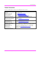
Table of Contents Table of Contents Page Chapter 1 About this Manual ...................................................................................................................... 1 Chapter 2 Product Overview....................................................................................................................... 2 2.1 Front Panel Interfaces ..................................................................................................... 2 2.2 Rear Panel Interfaces .............
About this Manual Chapter 1 About this Manual This manual describes the Magenta MultiView™ II XRTx transmitter (hereafter referred to simply as “XRTx”) and contains the following information: • • • • • Product overview (Chapter 2) Product specifications (Chapter 3) Installation and configuration instructions (Chapter 4) Troubleshooting (Chapter 5) Additional information (Appendices) The Magenta MultiView™ II family of products introduces greater compatibility for handling HD video standards, as well as
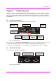
Product Overview Chapter 2 Product Overview The XRTx is a video transmitter compatible with the entire Magenta MultiView™ family of products. It extends an analog video signal over standard CAT5 cable (also CAT5e and CAT6). There are user-configurable settings for video, audio, and serial options which can be controlled from the front panel. When used with the appropriate receivers, the XRTx delivers the world’s longest UTP extension capability at the highest resolution—1920x1200 at 2000ft/609m. 2.
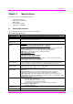
Specifications Chapter 3 Specifications This section describes the following specifications: • • • • • 3.1 General specifications VGA interface specifications DDC support Auxiliary signal support CAT5 cable compatibility General Specifications The following table lists the general specifications of the XRTx. Table 2: XRTx General Specifications Item Description Cable Required Compliance Video Support Category 5, 5e, 6 cable. Shielded or unshielded twisted pair. Low-skew preferred.
Specifications Item Description Enclosure Power Steel, black powder-coat finish. Input voltage: +5 VDC @ 1.2 Amps max. Consumption: 6 watts maximum 1.2"H x 4.2"W x 4.3"D (3.1 x 10.4 x 10.9 cm) 1.0 lb. (0.45 kg) 100,000 hours Size Weight MTBF 3.2 VGA Interface Specifications The following table describes the specifications of the VGA interface (video-in and local video-out).
Specifications 3.3 DDC Support For best compatibility with source devices (e.g. a PC), an extension device (XRTx in this case) should provide an appropriate DDC profile with the proper resolution and timing information. This helps ensure best compatibility with display devices connected at the remote end.
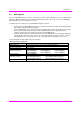
Specifications 3.4 Auxiliary Signal Support The XRTx is available in three factory-configured models and two user-configurable units, which allow different types of signals to be passed over the 4th-pair on the CAT5 cable. These are configured differently by a frontpanel setting, or may include an internal hardware option-module. The following table describes the different versions of XRTx.
Specifications 3.4.2 Auxiliary Signal Support: (232) Version The XRTx-232 comes equipped with an internal hardware (232) option module, enabling full-duplex RS-232 serial. This includes hardware handshaking signal support. Note that the (232) module itself does have some user-configurable settings which must be selected by internal jumpers (not through the front-panel buttons). It is important to set these internal jumpers correctly for your specific application. For more information, see Appendix-B.
Specifications 3.4.4 Auxiliary Signal Support: (SAP) Version The XRTx-SAP comes equipped with an internal hardware (SAP) option module, enabling full-duplex RS-232 serial (no hardware handshaking signals) and stereo audio. Note that the (SAP) module itself does have some user-configurable settings that can be changed by on-board DIP-switches (not through the front-panel buttons). The following table describes features of the XRTx-SAP.
Specifications Standard CAT6 cable, due to the manufacture method, will require the addition of our skew-compensation module option. Some CAT6 cable can exhibit much greater skew than standard CAT6 and may require skew compensation beyond what the standard product offers. Please contact Magenta Research for assistance. The CAT5/5e/6 cable should be suitably rated Listed cable (DUZX) communication cables, TYPE CMP, CMR, CMG or CM as designated in the NEC.
Installation Chapter 4 Installation CAT5/5e/6 cabling for the Magenta MultiView™ II Series must be pinned to the TIA-EIA T568B wiring specification. Figure 3: T568B CAT5 Specification We also highly recommend that all CAT5 cables be pre-terminated and tested. Cables terminated on-site or in an existing infrastructure should be tested before use to ensure compliance with the TIA-EIA T568B specification. Using incorrectly terminated CAT5 cables can damage the Magenta MultiView™ II Series.
Installation 4.2 Installation Procedure All units must be the same type for all auxiliary features to function correctly. For example, an “XRTx-232” transmitter must be connected to a MultiView™ II “-232” type receiver for the serial interface to function properly. You cannot mix one version of an XRTx with a different version of a MultiView™ II receiver. Video modes may function normally, but 4th pair options will not.
Installation To install the XRTx at the receiver end (these steps are generic - refer to the appropriate receiver manual): 1. Connect the VIDEO OUTPUT connector to the display, and attach any audio (AUX I/O) and/or serial connections (IOIO) depending on the model of MultiView™ II receiver and option module installed. 2. Connect the CAT5 cable to the LINK IN connector. If you are daisy-chaining multiple receivers, also connect the downstream CAT5 cable to the LINK OUT port on the receiver. 3.
Installation 4.3 Configuration This section describes how to configure the following settings: • • 4.3.1 User-configurable settings DDC settings User-Configurable Settings The XRTx has a number of configurable operating parameters, and the factory-default settings will work in most applications. However, some applications may require configuration changes. Nearly all settings are available from the front-panel buttons/LEDs.
Installation 4.3.2 DDC Settings These settings are accessed in NORMAL operating mode (CFG indicator is off). The MultiView™ II XRTx features the ability to send DDC display identifiers to the video source in order to determine display capabilities. The DDC interface is a data communication channel used between plug and play devices to accurately report a display's capabilities and identify the manufacturer.
Installation 4.4 Sync Settings The XRTx is factory-configured for auto-detecting the proper sync-mode (RepliSync-I normal/stretched). This mode is generally compatible with all existing MultiView™ and MultiView™ II receiver products that support RepliSync (if they are also using their factory-default settings). However, some video sources may require a custom sync-mode setting (most especially at 1080p and 1920x1200 video resolutions).
Installation 4th Pair Settings 4.5 The XRTx provides several options for using the 4th-pair signals (pairs 1-3 are generally used for video). Note that any connected MultiView™ or MultiView™ II receiver must be configured with a matching 4th-pair operating mode. Otherwise, the desired 4th-pair signal will not work as expected. th If an optional daughterboard is installed (232, SA or SAP options), then the 4 -pair utilization is defined by the installed daughterboard.
Installation 4.6 Video Coupling Settings The video input for the XRTx can be configured for AC coupling (with or without DC-restore function), DC coupling, or auto-detect. Perform the procedure below while the transmitter is in the normal operating state (CFG indicator is off): 1. Press and release the CFG button twice to access configuration-mode-2 (CFG indicator is flashing). 2. Press and release the SEL button once. You will now be able to change video-coupling settings. 3.
Troubleshooting Chapter 5 Troubleshooting In most cases, nearly every issue with the MultiView™ II CAT5 Video System can be resolved by checking the CAT5 termination and making sure that it’s pinned to the TIA/EIA 568B wiring specification. However, there may be other problems that cause the system to not perform as it’s designed. The following table lists the most common installation errors and their solutions.
Troubleshooting Problem Solution • When using SAP units, a maximum of 12 units may be daisy chained within the rated cable length of the receiver if using standard CAT5/6 or a maximum of 8 units may be daisy chained within the rated cable length of the receiver if using low-skew cable. • When daisy chaining, the maximum cable distance is not increased beyond the rated distance of the receiver used. For example, an AK600 can only daisy chain within 600 ft of the transmitter.
Connector Pinouts Appendix A Connector Pinouts Serial port (IOIO) Connector Pinout (232/SA/SAP versions only) The XRTx’s serial port connector is configured to look like a standard 9-pin “DCE” serial port. Therefore, in most applications a straight through serial cable or adapter-plug (DB9-Female-to-Male) is used to connect an external serial device (for example, a PC) to the XRTx transmitter.
Connector Pinouts Auxiliary I/O (AUX-I/O) Connector Pinout Pin #1 Pin #4 Figure 5: 4-pin Phoenix Connector Pinout Table 17: 4-pin Phoenix Pins XRTx PIN# 1 (SIG1) 2 (GND) 3 (SIG2) 4 (GND) XRTx-232 XRTx-SA XRTx-SAP Composite Video - SA Audio* SAP Audio Signal + Signal + - Left Channel Left Channel ground Signal - Signal - - Ground Ground Right Channel - - - - Right Channel Right Channel - Shell - - - - - (A) Audio (S) Simplex Serial SPDIF Audio Left Channel Tx Ground
Connector Pinouts DC Power Connector Magenta provides ready-to-use power supplies for MultiView™ II products. However, if there is a reason a substitute power supply must be used, then the following information is important for maintaining product reliability and performance: Magenta AC/DC Power supply output rating: Regulated +5VDC @ 3Amps. Power-input rating for MultiView™ II XRTx: 5VDC, 1.2Amps max.
Connector Pinouts RJ45 (MultiView Link) Wiring Standard T568B CAT5 Specification Figure 8: T568B CAT5 Table 18: T568B CAT5 Pins PIN # COLOR PAIR 1 White / Orange Stripe 2 2 Orange Solid 2 3 White / Green Stripe 3 4 Blue Solid 1 5 White / Blue Stripe 1 6 Green Solid 3 7 White / Brown Stripe 4 8 Brown Solid 4 Pins on plug face (socket is reversed) Figure 9: Typical RJ-45 Plug MultiView™ II XRTx Installation and User Guide 23
Connector Pinouts VGA Input/Output (optional) Connector Pinout The XRTx’s VGA port connectors are standard HD-15 female connectors (three-row, 15-pin).
Option Module Settings: XRTx-232 Appendix B Option Module Settings: XRTx-232 The (232) option module has internal jumper settings that can be configured for various serial modes and CAT5 cable lengths. To access the (232) module board: 1. 2. 3. 4. 5. 6. Example of jumper-plugs Make sure the unit is powered OFF. If necessary, unplug all cables to the unit. Unscrew the top cover screws. Unscrew the DB9-F hex-standoffs. Lift the cover off. Carefully unplug the (232) module from the main board.
Option Module Settings: XRTx-232 JP4 Pins JP2 Pins Table 21: Receiver (232) Module Jumper Settings Mode Type 1 Simplex (one way) (to 1500 ft) 2 Full Duplex (2 way) Short (< 500 ft) Baud (Max) 115k 19.2k Full Duplex (2 way) Long (to 1000 ft) 19.2k 4 Half Duplex (2 way) Long (to 1500 ft) 115k 5 Default Full Duplex (2 way) Long (to 1500 ft) 19.
Option Module Settings: XRTx-SAP Appendix C Option Module Settings: XRTx-SAP The SAP option module allows a bi-directional session to be established between a SAP-equipped transmitter (XRTx-SAP), and a specific SAP-equipped receiver even in a multiple-receiver daisy chain installation. The SAP transmitter devices (XRTx-SAP for example) do not have address DIP-switches. The factory-default address of the transmitter is “0”. The SAP receiver devices (AK600-SAP for example) have address DIP-switches.
Option Module Settings: XRTx-SAP SAP Addressing Chart ADDR 00 01 02 03 04 05 06 07 08 09 10 11 12 13 14 15 16 17 18 19 20 21 22 23 24 25 26 27 28 29 30 31 Switch Settings 1 ADDR 2 3 4 5 6 7 ON 8 OFF 2 3 4 5 6 7 8 ON OFF 33 3 4 5 6 7 8 ON OFF 34 3 4 5 6 7 8 ON OFF 35 4 5 6 7 8 ON OFF 36 4 5 6 7 8 ON OFF 37 4 5 6 7 8 ON OFF 38 4 5 6 7 8 ON OFF 39 5 6 7 8 ON OFF 40 5 6 7 8 ON OFF 41 5 6 7 8 ON OFF 42 5 6 7 8 ON OFF 43 5 6
Option Module Settings: XRTx-SAP SAP Addressing Chart (cont’d) ADDR 128 129 130 131 132 133 134 135 136 137 138 139 140 141 142 143 144 145 146 147 148 149 150 151 152 153 154 155 156 157 158 159 Switch Settings ADDR 8 1 2 3 4 5 6 7 2 3 4 5 6 7 3 4 5 6 7 3 4 5 6 7 4 5 6 7 4 5 6 7 4 5 6 7 4 5 6 7 5 6 7 5 6 7 5 6 7 5 6 7 5 6 7 5 6 7 5 6 7 5 6 7 6 7 6 7 6 7 6 7 6 7 6 7 6 7 6 7 6 7 6 7 6 7 6 7 6 7 6 7 6 7 6 7 1
Mounting Kits Appendix D Mounting Kits The following table shows several kits available for mounting the XRTx. Table 22: XRTx Mounting Kits Mounting Kit # 2211053-01 Description Rigid-mount bracket. This mounts a single device to a surface (wall/desk/etc.). Comes with 4 self-tapping screws. 8310207-02 1U Rack-mount Plate for standard 19” rack. Mounts 4 devices in a 1U space. Comes with (8) device-mounting screws, (4) rack-mounting screws. 8310208-02 2U Rack-mount Plate for standard 19” rack.
Mounting Kits Note: When installing XRTx devices in an area susceptible to elevated operating temperatures (near the maximum specified operating temperature), it is important to give careful consideration to maintaining adequate air flow. Within a rack assembly, cable bundles and other equipment in the same rack can impede proper cooling. In some rack-mount applications you may even need to leave a 1U gap (using a blank filler plate) between XRTx groups.
System Design Drawings Appendix E System Design Drawings The following drawings are available from Magenta Research as an aid in system design and configuration. You may download them from the Magenta website (www.magenta-research.com). There is no charge for obtaining these drawings. Table 23: MultiView™ II XRTx Drawings Drawing # 2500132-01 2510002-01 Description MultiView™ II XRTx Sales Drawing (.dwg and .pdf format) MultiView™ II XRTx Autocad Symbols (.dwg and .
Regulatory Compliance Information Appendix F Regulatory Compliance Information FEDERAL COMMUNICATIONS COMMISSION AND INDUSTRY CANADA RADIO FREQUENCY INTERFERENCE STATEMENTS This device complies with part 15 of the FCC Rules. Operation is subject to the following two conditions: 1) This device may not cause harmful interference, and 2) this device must accept any interference received, including interference that may cause undesired operation.
INDEX INDEX About this manual, 1 Configuration 4th-pair modes, 16 DDC modes, 14 factory defaults, 13 general modes, 13 sync modes, 15 video coupling modes, 17 video termination modes, 17 serial port, 20 UTP/CAT5 link port, 23 Precautions, iii Product overview, 2 Rear panel interfaces, 2 Regulatory information, 33 Reset to factory defaults, 13 Contact information, iv SAP addresses, 28 Default settings, 13 Serial addressing, 27 Drawings, 32 Specifications auxiliary signals, 6 CAT5 cables, 8 DDC suppor