
User guide

Installation
MultiView™ II XRTx Installation and User Guide 11
4.2 Installation Procedure
All units must be the same type for all auxiliary features to function correctly. For example,
an “XRTx-232” transmitter must be connected to a MultiView™ II “-232” type receiver for the
serial interface to function properly. You cannot mix one version of an XRTx with a different
version of a MultiView™ II receiver. Video modes may function normally, but 4th pair
options will not.
Ensure all connectors are clean and free of contaminants prior to making the connections.
Appropriate connector locking hardware (screws/latches) should be used to prevent cables
from disconnecting or causing intermittent operation.
To install the XRTx at the transmitter end:
1. Connect the source video to the Magenta MultiView™ II Series transmitter video input
port, which is a standard VGA connector labeled VGA IN.
2. If desired, attach a local monitor to the VGA connector labeled LOCAL OUT.
3. Connect the CAT5 cable to the transmitter LINK OUT port.
4. Make your audio or serial connections via the phoenix AUX I/O connector or DB9
“IOIO” serial connector, as appropriate for your XRTx transmitter model.
5. Connect the DC power cable (+5VDC @ 3A. max) to the POWER port.
6. Apply power on the transmitter.
a. The power-on LED should turn on. All other LEDs should execute a power-up
test sequence.
b. If the video source is providing a valid video signal, the video-status indicator
should turn on.
c. If there is a local monitor attached, a video image should appear on the
monitor.
7. Remember to make any required configuration changes via the LED/button user-interface.
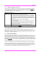
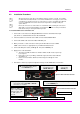
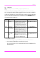
Figure 4: XRTx Transmitter Rear View
Connect the CAT5 cable to
the LINK OUT port.
(Optional) Connect
local display to the
LOCAL OUT
port.
Connect a video
source to the
VGA IN port.
Note: The DB9 serial
port is only available
when the “232”, “SA”
or “SAP” option is
present.
(Optional) Make your serial and/or audio
connections via the DB9 IOIO or AUX I/O
connector
s,
as
needed
.
Connect the DC power cable (+5VDC @ 3A. max)
to the
POWER
port.
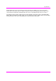
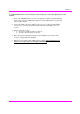
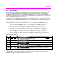
Power-on indicator
Video status and DDC
-
copy indicator
Operating mode:
Off
=normal,
On
=config
Figure 5: XRTx Transmitter Front View