
User guide

Troubleshooting
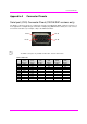
MultiView™ II XRTx Installation and User Guide 18
Chapter 5 Troubleshooting
In most cases, nearly every issue with the MultiView™ II CAT5 Video System can be resolved by checking the
CAT5 termination and making sure that it’s pinned to the TIA/EIA 568B wiring specification. However, there may
be other problems that cause the system to not perform as it’s designed. The following table lists the most
common installation errors and their solutions.
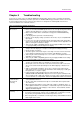
Table 15: Troubleshooting Problems and Solutions
Problem Solution
No video signal at
the receiver
•
Check that both units are powered.
• Ensure receiver EQ and SKEW adjustments are set correctly. Change EQ settings
slowly to allow the display to re-acquire a valid signal and display the image.
• Make sure the CAT5 cable is terminated correctly per the TIA/EIA 568B wiring
specification.
• Is the display device powered on and functioning?
• Check to ensure display settings (resolution, refresh rate, etc) are compatible with
input signal.
• In some cases, the video termination may be mismatched. Generally, transmitters
and receivers ship with 75-ohm termination as the default. Refer to applicable user-
guides to change the termination settings.
• There may be a DDC compatibility problem. Try changing the DDC mode setting,
or copying the DDC profile directly from the display.
Poor video quality at
receiver
•
Ensure receiver EQ and SKEW adjustments are set correctly. Change EQ settings
slowly to allow the display to re-acquire a valid signal and display the image.
• Check all cable connections.
• The video signal’s refresh rate may be set too high. Reset to a lower refresh rate
in your display-configuration menu (for example, under Windows on a PC).
• There may be a video-skew delay issue. See section on skew adjustments in the
applicable receiver manual.
• There may be a DDC compatibility problem. Try changing the DDC mode setting,
or copying the DDC profile
directly from the display.
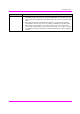
Poor audio quality
•
The audio output at the receiver is line-level only. An amplifier or powered
speakers are required. Make sure amplifier or speaker power is ON.
• Check input source levels from the source device. Ensure the audio source level
does not exceed the audio-input ratings for the XRTx. Clipping or distortion can
result.
• Audio is summed left and right for “A” versions. If using a single channel, both
audio inputs must be connected at the transmitter end to obtain proper audio gain
through the link (1:1, input to output).
• If daisy chaining, audio termination must be removed in DP receivers
(AK600/1200DP and XR2000DP). Only the last receiver requires termination. This
does not apply to SA or SAP units. SA units no longer require separate daisy chain
or end of line units as of April 2009. Refer to the appropriate receiver user manual.
Serial
communication
doesn’t work
correctly
•
Are the serial devices connected properly? Are the serial parameters correct for
source/destination devices?
• Are the serial cables terminated correctly? Is a null-modem cable required at the
TX or RX end?
• When using RS-232 capable receivers with video switches, distribution amps, or
multi-output transmitters, the serial data is sent transmit-only. Please take this into
account when trying to control displays or other devices. For assistance, contact
Magenta Technical Support.
Notes on daisy
chaining
When utilizing a receiver’s RJ45 daisy chain port, the following rules apply:
•
If using L/R summed audio, simplex serial, or SPDIF units, a maximum of 12 units
may be daisy changed within the rated cable length of the receiver.
•
When using SA units, a maximum of 4 units may be daisy chained within the rated
cable length of the receiver.