. Connect with Confidence MultiView 500A / 500S Receiver Quick Reference & Setup Guide Magenta Research 128 Litchfield Road, New Milford, CT 06776 USA (860) 210-0546 FAX (860) 210-1758 www.magenta-research.
MAGENTA MULTIVIEW™ SERIES © 1998-2010 by Magenta Research All rights reserved. Magenta Research 128 Litchfield Road New Milford, CT 06776 USA This document and the Magenta Research products to which it relates, and the copyright in each, is the property of Magenta Research. Neither the document nor the products may be reproduced by any means, in whole or in part, without the prior written permission of Magenta Research.
CONTENTs. Contents Chapter Page 1. Specifications...................................................................................................2 2. Introduction ........................................….........................................................3 2.1 Overview................................................................................….................3 2.2 Equipment You May Also Need..........................................................…....3 2.3 Compatible Cabling .........
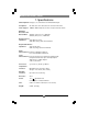
MAGENTA MULTIVIEW™ SERIES 1. Specifications Cable Required: Category 5, 5e, 6 shielded or unshielded twisted pair Compliance: CE; FCC Class A, IC Class/class A, UL listed I.T.E Device Video Support: RGBHV, RGB, Composite, S-Video, Component Video modes Maximum Resolution and Refresh Rate: At 500 ft.
CHAPTER 2: Introduction. 2. Introduction 2.1 Overview Magenta’s MultiView™ CAT5 Video System MultiView series extends VGA and audio signals over ordinary Category 5 cable. This manual covers the Magenta MultiView™ 500A CAT5 Video System Series Receiver with audio and the MultiView 500S receiver with RS232 serial support. For information on the respective transmitter unit, please refer to the appropriate manual included with the transmitter.
MAGENTA MULTIVIEW™ SERIES 3. Setup and Installation 3.1 Cabling Considerations • We recommend mounting and connecting all cabling to the MultiView™ Series components before applying power. • Make sure that the CAT5 cable you intend to use has been tested to comply with the T568B wiring specification (See Appendix A). 3.2 Making the Connections 3.2.1 CONNECTIONS AND SETUP IN GENERAL First ensure all units have been configured for correct operation and signal types.
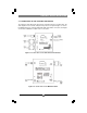
CHAPTER 3: SETUP & INSTALLATION. 3.2.2 CONNECTIONS ON THE VGA/AUDIO TRANSMITTER The single-port units with audio support video and audio signals over CAT5 cable. The audio signal is line-level audio, and powered speakers are required. Figure 3-1 shows the MultiView™ Series UTx transmitter with Audio Transmitter connections, and Figure 3-2 shows the MultiView™ 500A receiver connections. Figure 3-1. Connections on the UTx Universal Transmitter. Figure 3-2. Connections on the MultiView 500A.
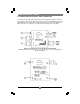
MAGENTA MULTIVIEW™ SERIES 3.2.3 CONNECTIONS ON THE VIDEO / SERIAL TRANSMITTER The single-port units with audio support video and serial signals over CAT5 cable. The serial signal is 3 wire TX, RX, GND serial. Figure 3-3 shows the MultiView™ Series UTx transmitter with serial Transmitter connections, and Figure 3-4 shows the MultiView™ 500S serial receiver connections. See Appendix A for cable pinouts of the 500S. Figure 3-3. Connections on the UTx Universal Transmitter.
CHAPTER 3: Setup and Installation. 3.3 Configuration Settings The MultiView™ 500 receiver is configurable for various video, audio and serial modes depending upon model . Note that a compatible transmitter unit must be used at the source end. Reference the appropriate transmitter user guide or call for technical assistance. It is not possible to change an audio unit to a serial unit and vice versa. A dipswitch on the receiver unit is used to set the video, audio, serial configuration mode.
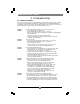
MAGENTA MULTIVIEW™ SERIES 4. Troubleshooting 4.1. Common Problems In most cases, nearly every issue with the MultiView™ CAT5 Video System can be resolved by checking the CAT5 termination and making sure that it’s pinned to the TIA/EIA 568B wiring specification. However, there may be other problems that cause the system to not perform as it’s designed. Below are solutions to the most common installation errors. Problem: Solution: No video signal at the transmitter local port or at the receiver.
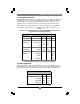
APPENDIX A: Cabling Pinouts. Appendix A. Cabling Pinouts Table A-1. HD15 video connector.
MAGENTA MULTIVIEW™ SERIES Appendix A. Cabling Pinouts Table A-2. T568B CAT5 pinout Table A-3. 1/8” (3.5 mm) Audio/Serial Connection (model dependent) Pin Signal Tip Serial Tx (DB9 pin3) Left Audio+ Ring Serial Rx (DB9 pin2) Right Audio+ Sleeve Serial GND (DB9 pin5) GND Note: The stereo audio input at the transmitter is summed and output as mono audio on both channels at the receiver.
APPENDIX B: Mounting Options. Appendix B. Mounting Options The Rackmount Kits include brackets for mounting a single transmitter, single receiver, or a single dual daisychainable receiver. Figure B-1 shows the 1-Unit Rackmount Bracket , which can be used to mount a single unit on a wall or in a 19” rackmount bracket. Figure B-2 shows the 4-Unit Rackmount Bracket, which holds four units in a 19" x 1U rack. The rigid mount bracket for the MultiView 500 series is incorporated into the top cover.
MAGENTA MULTIVIEW™ SERIES NOTES 12
. NOTES 13
MAGENTA MULTIVIEW™ SERIES Magenta Research 128 Litchfield Road, New Milford, CT 06776 USA (860) 210-0546 FAX (860) 210-1758 www.magenta-research.