
Setup guide

14
MAGENTA MULTIVIEW™ SERIES
12
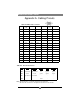
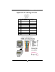
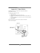
Appendix A. Cabling Pinouts
Table A-1. HD15 video connector.
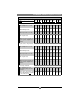
Table A-2. Phoenix Connection
Note: Typically Channel 1 is left audio and Channel 2 is right audio.
SA series units use Channel 1 for Right audio and channel 2 for left audio.
Pin RGBHV
(VGA)
RGBS RGsB Com-posite SVHS
(Y/C)
YUV
1 Red + Red + Red + C+ V+
2 Green+ Green+ Green+ C+ Y+ Y+
3 Blue+ Blue+ Blue+ U+
4 — — —
5 Gnd Gnd Gnd
6 Red- Red- Red- C- V-
7 Green- Green- Green- C- Y- Y-
8 Blue- Blue- Blue- U-
9 — — —
10 Gnd Gnd —
11 Gnd Gnd —
12 — — —
13 H Sync C Sync —
14 V Sync — —
15 Gnd Gnd —
PIN Audio SA / SAP
Audio
Simplex
Serial
SPDIF
Audio
Composite
Video
Pin 1
Left Channel Right Channel Tx Signal + Signal +
Pin 2
Ground Ground ground Signal - Signal -
Pin 3
Right Channel Left Channel - - -
Pin 4
- Shell - -