. MultiView XR2000 Receiver Quick Reference & Setup Guide Magenta Research 128 Litchfield Road, New Milford, CT 06776 USA (860) 210-0546 FAX (860) 210-1758 www.magenta-research.
MAGENTA MULTIVIEW™ SERIES © 1998-2008 by Magenta Research All rights reserved. Magenta Research 128 Litchfield Road New Milford, CT 06776 USA This document and the Magenta Research products to which it relates, and the copyright in each, is the property of Magenta Research. Neither the document nor the products may be reproduced by any means, in whole or in part, without the prior written permission of Magenta Research.
FCC/IC RFI STATEMENTS, EU DECLARATION OF CONFORMITY. FEDERAL COMMUNICATIONS COMMISSION AND INDUSTRY CANADA RADIO FREQUENCY INTERFERENCE STATEMENTS This equipment generates, uses, and can radiate radio-frequency energy, and if not installed and used properly, that is, in strict accordance with the manufacturer’s instructions, may cause interference to radio communication.
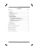
MAGENTA MULTIVIEW™ SERIES Contents Chapter Page 1. Specifications...................................................................................................3 2. Introduction ........................................…..........................................................4 2.1 Overview.....................................................................................................4 2.2 Equipment You May Also Need..........................................................…....4 2.
CHAPTER 1: Specifications. 1. Specifications Cable Required: Category 5, 5e, 6 shielded or unshielded twisted pair Compliance: CE; FCC Class A, IC Class A Video Support: QVGA, VGA, SVGA, XGA, SXGA, UXGA, RGBHV, RGB, Composite (NTSC, PAL, SECAM), S-Video, Component Video, widescreen modes, HDTV modes including 1080p, 1080i, 720p Resolution and Refresh Rate: At 2000 ft.
MAGENTA MULTIVIEW™ SERIES 2. Introduction 2.1 Overview The Magenta MultiView Series extends video, audio and serial signals over ordinary Category 5 cable. This manual covers Magenta MultiView Series XR2000 Receivers. These units are field configurable for various video, audio and serial options. See Appendix B for configuration settings. SA series feature video, stereo audio and RS-232 signals on a single cat5. SAP series units are similar to the above but have additional features for pollable serial.
CHAPTER 3: SETUP & INSTALLATION. 3. Setup and Installation 3.1 Data Mode Configuration SA series offer RS232 serial in addition to stereo audio. The serial signal is 3 wire TX, RX, GND and does not support full modem signals. Baud rates for the SA series are fixed at 9600. Simplex modes are supported without jumper or other changes by simply using the TX signal only. SA units require no configuration. SAP series offer pollable RS232 serial in addition to stereo audio.
MAGENTA MULTIVIEW™ SERIES 4. Connect the CAT5 cable to the transmitter. 5. Apply power on the transmitter. The LED should light and, if there’s a local monitor attached, a video image should appear on the monitor’s screen. At the receiver end: 1. Connect the VIDEO OUT HD15 connector to the display unit, and attach any audio (AUX I/O) or serial connections (IOIO) depending on the model of MultiView CAT5 Video System. 2. Connect the CAT5 cable to the LINK INPUT connection.
CHAPTER 3: Setup and Installation. 3.3.3 CONNECTIONS ON THE SINGLE-PORT VGA SA and SAP The Single-Port MultiView™ CAT5 Video System SA/SAP series supports RS-232, video and stereo audio signals over CAT5 cable. SAP offers pollable serial modes so a bi-directional serial session can be established with a receiver in a daisy chain. At this time the Magenta MultiView units that support the SA/SAP versions are the Magenta MultiView UTx Universal Transmitter, AK500, AK1000, AK1500 and XR2000 receivers.
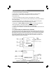
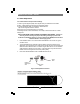
MAGENTA MULTIVIEW™ SERIES 3.4 Video Adjustment 3.4.1 Cable Distance Compensation Settings In order to get the highest quality video signals from your MultiView CAT5 Video System , please follow the instructions and diagrams below: An Image Adjustment Utility is available for download from: http:// www.magenta-research.com/test Simply open in any image browser on a computer. If the image file can not be downloaded, use a utility to draw a black box on a white background.
CHAPTER 3: Setup and Installation. 3.4.2 Skew Compensation Settings The XR2000 receiver is available with an optional skew compensation module to adjust for signal timing differences due to differing pair lengths within the CAT5 cable. Using the delay signals, skew may be compensated from 2 to 65 nanoseconds in 2 nanosecond increments on each individual color pair. If skew compensation is required, but the skew comp module is not installed, call for technical assistance.
MAGENTA MULTIVIEW™ SERIES 4. Troubleshooting 4.1. Common Problems In most cases, nearly every issue with the MultiView CAT5 Video System can be resolved by checking the CAT5 termination and making sure that it’s pinned to the TIA/EIA 568B wiring specification. However, there may be other problems that cause the system to not perform as it’s designed. Below are solutions to the most common installation errors. Problem: Solution: No video signal at the transmitter local port or at the receiver.
CHAPTER 4: Troubleshooting. Problem: Solution: Poor audio quality (continued) : • If Daisy Chaining, audio termination must be removed in DP units. Only the last receiver requires termination. For SA units a special un-terminated version must be used between transmitters and the last receiver with a standard End-Of-Line unit installed at the end. SA units cannot be terminated/ unterminated in the field. This does not apply to SAP units. Problem: Solution: Serial communication doesn’t work correctly.
MAGENTA MULTIVIEW™ SERIES Appendix A. Cabling Pinouts Table A-1. HD15 video connector. Pin RGBHV (VGA) RGBS RGsB Com-posite 1 Red + Red + Red + 2 Green+ Green+ Green+ 3 Blue+ Blue+ Blue+ 4 — — — 5 Gnd Gnd Gnd 6 Red- Red- Red- 7 Green- Green- Green- 8 Blue- Blue- Blue- 9 — — — 10 Gnd Gnd — 11 Gnd Gnd — 12 — — — 13 H Sync C Sync — 14 V Sync — — 15 Gnd Gnd — SVHS (Y/C) YUV C+ V+ Y+ Y+ C+ U+ C- C- V- Y- YU- Table A-2.
APPENDIX A: Cabling Pinouts. Appendix A. Cabling Pinouts Table A-3. DB9 Male Serial connector Pin 3 wire (SA/SAP) Simplex 1 2 RX 3 TX TX Ground Ground 4 5 6 7 8 9 Table A-4.
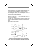
MAGENTA MULTIVIEW™ SERIES Appendix B. XR2000 Configuration Settings Note: XR2000 receivers are typically pre-configured at time of order and will have factory configuration indicated on the bottom of the unit. The factory configuration may be changed or checked by using the following jumper location diagram as well as Table B-1 for jumper settings. Figure B-1. XR2000 Jumper locations.
APPENDIX B: XR2000 Configuration Settings.
MAGENTA MULTIVIEW™ SERIES Appendix C. Setting Sync Mode The XR2000 has the capability for fixed and agile sync. The default sync mode setting is for agile sync which replicates the source sync polarity signals. However some displays require a fixed sync polarity that is not possible to change at the video source.
APPENDIX D: Skew Compensation Module. Appendix D. Skew Module The XR2000 receivers have an optional skew compensation module that can be installed or removed. To install the skew compensation module: 1 2 4 5 6 Remove top cover. Remove the 3 jumpers from J16 pins 1-2, 4-5, 7-8. Insert the Skew assembly onto the XR series PCB using 11 pin headers J16 and J17. The correct orientation of the skew board is to place the side with the Magenta logo into header J17. Reassemble unit.
MAGENTA MULTIVIEW™ SERIES Appendix E. Rackmounting Units The Rackmount Kits include brackets for mounting a single transmitter, single receiver, or a single dual daisychainable receiver. Figure E-1 shows the 1-Unit Rackmount Bracket , which can be used to mount a single unit on a wall. Figure E-2 shows the 4-Unit Rackmount Bracket, which holds four units in a 19" x 1U rack. Not shown are brackets for 6 units and brackets for AK and XR series receivers, T4 transmitters.
APPENDIX F: Pollable Serial Mode. Appendix F. Pollable Serial Mode The SAP pollable serial daisychainable receivers with video, audio and RS232 serial feature the ability to open a bi-directional session between a pollable transmitter and a single pollable receiver in a daisychain installation. Each pollable receiver must have a unique address set first. Once this has been done, a special command (discussed below) is sent to the transmitter to specify the receiver to open a session with.
MAGENTA MULTIVIEW™ SERIES Appendix F.
APPENDIX F: Pollable Serial Mode. Appendix F. Pollable Serial Mode Address Chart (cont.
MAGENTA MULTIVIEW™ SERIES Magenta Research 128 Litchfield Road, New Milford, CT 06776 USA (860) 210-0546 FAX (860) 210-1758 www.magenta-research.