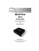
. Connect with Confidence MultiView XRTx Transmitter Quick Reference & Setup Guide Magenta Research 128 Litchfield Road, New Milford, CT 06776 USA (860) 210-0546 FAX (860) 210-1758 www.magenta-research.
MAGENTA MULTIVIEW™ SERIES © 1998-2009 by Magenta Research All rights reserved. Magenta Research 128 Litchfield Road New Milford, CT 06776 USA This document and the Magenta Research products to which it relates, and the copyright in each, is the property of Magenta Research. Neither the document nor the products may be reproduced by any means, in whole or in part, without the prior written permission of Magenta Research.
FCC/IC RFI STATEMENTS, EU DECLARATION OF CONFORMITY. FEDERAL COMMUNICATIONS COMMISSION AND INDUSTRY CANADA RADIO FREQUENCY INTERFERENCE STATEMENTS This equipment generates, uses, and can radiate radio-frequency energy, and if not installed and used properly, that is, in strict accordance with the manufacturer’s instructions, may cause interference to radio communication.
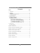
MAGENTA MULTIVIEW™ SERIES Contents Chapter Page 1. Specifications...................................................................................................3 2. Introduction ........................................…..........................................................4 2.1 Overview.....................................................................................................4 2.2 Equipment You May Also Need..........................................................…....4 2.
CHAPTER 1: Specifications. 1.Specifications Cable Required: Category 5, 5e, 6 shielded or unshielded twisted pair Compliance: CE; FCC Class A, IC Class/class A Video Support: VGA, SVGA, XGA, XGA-2, RGBHV, RGB, Composite, S-Video, Component Video modes Resolution and Refresh Rate: Up to 2048 x 1536 at up to 72 Hz (receiver dependent) Required Source Impedance: Video OUT: 75 ohms; Audio models: Audio OUT (if any): 600 ohms maximum SPDIF audio models: 75 Ohm.
MAGENTA MULTIVIEW™ SERIES 2. Introduction 2.1 Overview The Magenta MultiView™ Series extends VGA and video signals over ordinary Category 5 cable. This manual covers Magenta MultiView™ XRTx Universal Transmitters. These units are field configurable for various video, audio and serial options. See Appendix D for configuration settings. The XRTx features the ability to report DDC information to the video source computer.
CHAPTER 3: SETUP & INSTALLATION. 3. Setup and Installation 3.1 Data Mode Configuration (RS232 and SA versions) XRTx 232 serial transmitters are configured in full modem bidirectional serial modes. If you are using the daisy chain receivers or a multi-output transmitter (T4,T5) a MultiView™ CAT5 matrix switch or MultiView™ CAT5 distribution amp, this mode must be changed to uni-directional broadcast .
MAGENTA MULTIVIEW™ SERIES 4. Connect the CAT5 cable to the transmitter. 5. Apply power on the transmitter. The LED should light and, if there’s a local monitor attached, a video image should appear on the monitor’s screen. At the receiver end (refer to the appropriate receiver manual): 1. Connect the VIDEO OUTPUT HD15 connector to the display unit, and attach any audio (AUX I/O) and/or serial connections (IOIO) depending on the model of MultiView™ CAT5 Video System. 2.
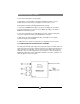
CHAPTER 3: Setup and Installation. Figure 3-2. Connections on the AK600 with audio. 3.3.3 CONNECTIONS ON THE SINGLE-PORT VGA/RS-232 The Single-Port MultiView™ CAT5 Video System with RS-232 supports video and fullmodem serial (RS-232) signals over CAT5 cable. You can also use the transmitters and receivers to make video-only connections without serial communications.
MAGENTA MULTIVIEW™ SERIES Figure 3-4. Receiver connections on the AK600 232 3.3.4 CONNECTIONS ON THE VGA/AUDIO T4/T5 TRANSMITTERS The T4 four-port transmitter is used when the same signal is distributed to multiple display devices. You set it up and cable it the same as you would with the single-port transmitter. Figure 3-5 shows how connections are made on the audio version, and Figure 3-6 shows how connections are made on the serial RS-232 T4S version. Figure 3-5.
CHAPTER 3: Setup and Installation. 3.3.5 CONNECTIONS ON THE SINGLE-PORT VGA SA and SAP The Single-Port MultiView™ CAT5 Video System SA/SAP series supports RS-232, video and stereo audio signals over CAT5 cable. SAP offers pollable serial modes so a bi-directional serial session can be established with a receiver in a daisy chain. At this time the Magenta MultiView units that support the SA/SAP versions are the Magenta MultiView XRTx & UTx Universal Transmitters, AK600, AK1200, and XR2000 receivers.
MAGENTA MULTIVIEW™ SERIES 4. Troubleshooting 4.1. Common Problems In most cases, nearly every issue with the MultiView™ CAT5 Video System can be resolved by checking the CAT5 termination and making sure that it’s pinned to the TIA/EIA 568B wiring specification. However, there may be other problems that cause the system to not perform as it’s designed. Below are solutions to the most common installation errors. Problem: Solution: No video signal at the transmitter local port or at the receiver.
CHAPTER 4: Troubleshooting. Problem: Solution: Serial communication doesn’t work correctly. • Are the serial devices connected properly? Are the serial parameters correct for source/destination devices? • Are the serial cables terminated correctly? If a null-modem cable is used, it must be placed at the receiver end. • When using RS-232 transmitters or receivers in daisy chains, Cat5 switches, Cat5 distribution amps, or Multi-output transmitters, the serial signal is a unidirectionally broadcast mode only.
MAGENTA MULTIVIEW™ SERIES Appendix A. Cabling Pinouts Table A-1. HD15 video connector. Pin RGBHV (VGA) RGBS RGsB Composite 1 Red + Red + Red + 2 Green+ Green+ Green+ 3 Blue+ Blue+ Blue+ 4 — — — 5 Gnd Gnd Gnd 6 Red- Red- Red- 7 Green- Green- Green- 8 Blue- Blue- Blue- 9 — — — 10 Gnd Gnd — 11 Gnd Gnd — 12 — — — 13 H Sync C Sync — 14 V Sync — — 15 Gnd Gnd — SVHS (Y/C) YUV C+ V+ Y+ Y+ C+ U+ C- C- V- Y- YU- Table A-2.
APPENDIX A: Cable Pinning. Appendix A. Cabling Pinouts Table A-3. DB9 Female Serial connector Pin Full Duplex 3 wire (SA/SAP) 1 DCD 2 RX RX 3 TX TX TX 4 DTR 5 Ground Ground Ground 6 DSR 7 RTS 8 CTS 9 RI Table A-4.
MAGENTA MULTIVIEW™ SERIES Appendix B. Setting Sync Signal Output Termination In some cases, it may be necessary to disable the 75-ohm termination of the video outputs on the MultiView™ CAT5 Video System units. This can be done by opening the case of each unit and installing jumpers on the circuit board. The settings disable/ enable the 75-ohm termination on individual units. For instance, changing a transmitter termination affects the local monitor port only, it doesn’t affect the receivers.
APPENDIX C: DC Restore. Appendix C. DC Restore to fix Green Shift of AC Coupled Signals The standard MultiView product is designed to function with DC coupled signals with the black level referenced to 0 volts. Nearly all VGA cards function this way. However, some media servers or digital camera devices provide AC coupled signals and can cause a green color shift in the video. This is a result of the sync clamping on the Red and Blue channels in the MultiView.
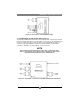
MAGENTA MULTIVIEW™ SERIES Appendix D. XRTx Configuration Settings Note: XRTx transmitters are typically pre-configured at time of order and will have factory configuration indicated in the part number label on the bottom of the unit. The factory configuration may be changed or checked by using the following jumper location diagram as well as Table D-1 for jumper settings.
APPENDIX D: XRTX Configuration Settings.
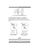
MAGENTA MULTIVIEW™ SERIES Appendix E. Serial Daughterboard (SDB) Settings The single-port serial transmitters and single-port and dual daisy chainable serial receivers contain an internal serial daughterboard (SDB) that can be configured for various serial modes. Multi Port Cat5 transmitters do not utilize the SDB and are configured for Mode 1 only. The SDB hardware configuration is done via jumper settings. These jumpers are used to set the various modes of operation. As shown below.
APPENDIX D: Serial Settings. Appendix E. Serial Daughterboard (SDB) Settings, cont Table D-2. Receiver SDB jumper settings Mode Type Baud (Max) JP1 JP2 1 Simplex (one way) (to 1500 ft) 115k 1-2 See Notes 3-4 See Notes 5-6 IN 7-8 OUT 9-10 OUT 1-2 IN 3-4 OUT 5-6 OUT 7-8 OUT 9-10 IN 2 Full Duplex (2 way) Short (< 500 ft) 19.2K 1-2 See Notes 3-4 See Notes 5-6 OUT 7-8 OUT 9-10 OUT 1-2 IN 3-4 OUT 5-6 OUT 7-8 IN 9-10 OUT 3 Full Duplex (2 way) Long (to 1000 ft) 19.
MAGENTA MULTIVIEW™ SERIES Appendix F. Rackmounting Units The Rackmount Kits include brackets for mounting a single transmitter, single receiver, or a single dual daisychainable receiver. Figure F-1 shows the 1-Unit Rackmount Bracket , which can be used to mount a single unit on a wall. Figure F-2 shows the 4-Unit Rackmount Bracket, which holds four units in a 19" x 1U rack. Not shown are brackets for 8 units and brackets for AK/XR series receivers and T4 transmitters.
APPENDIX F: Pollable Serial Mode. Appendix G. Pollable Serial Mode The SAP pollable serial daisychainable receivers with video, audio and RS232 serial feature the ability to open a bi-directional session between a pollable transmitter and a single pollable receiver in a daisychain installation. Each pollable receiver must have a unique address set first. Once this has been done, a special command (discussed below) is sent to the transmitter to specify the receiver to open a session with.
MAGENTA MULTIVIEW™ SERIES Appendix G.
APPENDIX F: Pollable Serial Mode. Appendix G. Pollable Serial Mode Address Chart (cont.
MAGENTA MULTIVIEW™ SERIES Appendix H. DDC Modes The MultiView XRTx features the ability to send DDC/EDID display identifiers to the video source in order to determine display capabilities. The DDC is a data communication channel used in plug and play devices to accurately report a displays capabilities and identify the manufacturer. If this data is not available, the video source may revert to a low resolution or not display at all.
APPENDIX I: Setting Sync Mode. Appendix I. Setting Sync Mode The XRTx has the capability for fixed and agile sync. The default sync mode setting is for agile sync which replicates the source sync polarity signals. However some displays require a fixed sync polarity that is not possible to change at the video source. NOTE: Both transmitter and receiver must have the same settings. Not all Magenta MultiView transmitter/receivers support this function. In this case Agile Sync Mode must be used.
MAGENTA MULTIVIEW™ SERIES Magenta Research 128 Litchfield Road, New Milford, CT 06776 USA (860) 210-0546 FAX (860) 210-1758 www.magenta-research.