
Owner's Manual


9
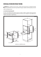
Figure 2
INSTALLATION INSTRUCTIONS
13�0”
(589 mm)
13�0” (589 mm)
13�0”
(589 mm)
13�0” (589 mm)
1�0”
(24 mm)
0�4”
(10 mm)
0�4” (10 mm)
22�5”
(570 mm)
22�0”
(558 mm)
23�5”
(590 mm)
22�5" - 23�0”
(575 mm
- 585 mm)
WARNING: Only a qualified service personnel in compliance with the instructions provided must install the
appliance� The manufacturer declines all responsibility for improper installation, which may harm persons and
animals and damage property�
LOCATION REQUIREMENTS
In order to ensure that the built-in appliance functions properly, the cabinet containing it must be appropriate�
The figures below and the next page give the dimensions of the cut-out for installation in a wall cabinet unit or
under the counter� (Refer to Figure 2 and 3�)
Installation in a Wall Cabinet Unit