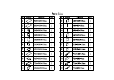
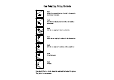
Parts List NO. Drawing Dimension QTY NO.
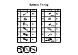
Hardware Fitting NO. Drawing A QTY NO. 50 G Drawing QTY 52 3.5*14mm B 58 H 8 C 8 I 8 3.0*14mm D 8 J 2 90*45mm 7*38mm E 4 K F 4 L 1 3.5*35mm 3.
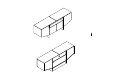
2 3 11 1 7 4 21 22 20 10 5 12 13 8 19 17 18 6 9 14 16 15
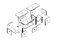
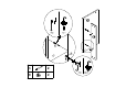
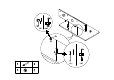
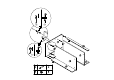
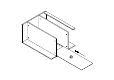
Cam Coupling Using Methods Step1. Connect the cam coupling A as directed in the assembly instructions using hand. step 1 Step2. Screw the cam coupling A as directed in the assembly instructions. step 2 Step3. Push the cam coupling A into the entry hole. step 3 Step4. Insert the cam coupling B as shown in the instructions. step 4 Step5. Turn the cam coupling B clockwise with a screwdriver step 5 Step6. Put on Beautycam. step 6 Step7. Finished.
10 step 1 step 2 19 A B A 2 step 1 B 2 step 2
21 step 1 step 2 8 B A A 2 B 2 step 1 step 2
step 1 step 2 A B 5 22 step 1 8 step 2 10 A 9 B 9 19 21
20
22 step 1 step 2 4 8 A 10 B 19 step 1 A 9 B 9 step 2
9 7 D D 8
step 1 step 2 A B A A step 1 step 2 6 A 11 12 C C 9 3 A 14 C 13 7 C C A 4 B 8 C 4
step 1 step 2 A B A step 1 4 A 13 step 2 11 C C C 7 A 2 B 4 C 2
step 1 step 2 A B step 1 A step 2 12 5 A 14 C C 9 C A 2 B 4 C 2
J G G 1 2 G 16 3.
A step 1 step 2 2 3 11 1 4 13 22 12 B 5 step 1 6 14 A 20 B 20 step 2
H Step1 8 H I 8 3.
L G L 3.5*35mm 3.5*14mm G 2 4 3.
F G G 15 E G G 16 18 17 E 4 F 4 G 16 3.
G G 15 17 G 16 3.
ø8*40 Step 1 WALL Step 2 L Step 3 L L *2 3.
L L *2