MP-7VIP-A Motherboard User’s Manual Product Name: MP-7VIP-A Manual Revision: English, 1.
Federal Communications Commission Statement This device complies with FCC Rules Part 15. Operation is subject to the following two conditions: w This device may not cause harmful interference w This device must accept any interference received, including interference that may cause undesired operation. This equipment has been tested and found to comply with the limits for a Class B digital device, pursuant to Part 15 of the FCC Rules.
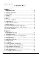
MAGIC-PRO MP-7VIP-A CONTENT Chapter 1 INTRODUCTION .......................................................... 4 1-1 ITEM LIST CHECKUP .................................................................. 4 1-2 PROCESSOR ............................................................................... 4 1-3 CHIPSET ...................................................................................... 4 1-4 MEMORY ...................................................................................... 5 1-5 BIOS ..
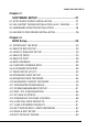
MAGIC-PRO MP-7VIP-A Chapter 3 SOFTWARE SETUP ................................................... 27 3-1 AC’97 AUDIO CODEC INSTALLATION ..................................... 27 3-2 VIA CHIPSET DRIVER INSTALLATION (4-IN-1 DRIVER)......... 27 3-3 HARDWARE MONITOR INSTALLATION .................................. 28 3-4 VIA USB FILTER DRIVER INSTALLATION ................................ 28 Chapter 4 BIOS Setup ................................................................ 29 4-1 INTRODUCE THE BIOS ...........
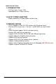
MAGIC-PRO MP-7VIP-A CHAPTER 1 INTRODUCTION 1-1 ITEM LIST CHECKUP • Motherboard • Support CD • User’s Manual • Temperature Sensor Cable • ATA66 IDE Cable • RS232 Cable 1-2 PROCESSOR • Supports AMD Athlon ThunderbirdTM 700MHz/ 750MHz/ 800MHz/ 850MHz/ 900MHz/ 950MHz/1.0GHz processors or higher. • Supports AMD Athlon DuronTM 600MHz/ 650MHz/ 700MHz processors or higher. • Supports 66MHz/ 100MHz/ 133MHz CPU Front Side Bus(FSB). • Supports processor voltage auto-detect circuit.
MAGIC-PRO MP-7VIP-A --- 100MHz DDR(Double Data Rate) transfer on Athlon CPU address and data buses. --- Supports full AGP v2.0 capability for maximum bus utilization including 1x, 2x, and 4x mode transfers. --- Both Windows 95 VxD and Windows 98 / Windows 2000 miniport drivers are supported for ineroperability with major AGP-based 3D and DVDcapable multimedia accelerators. 1-4 MEMORY • Supports PC133 and PC100 SDRAM and Virtual Channel Memory (VCM) up to 3 DIMMs. • Supports up to 1.
MAGIC-PRO MP-7VIP-A 1-7 FORM FACTOR • ATX form factor, 4 layers PCB. • Motherboard size: 22.0cm x 30.5cm 1-8 AC’97 CODEC FUNCTION • Adopts onboard AC’97 Audio Codec controller chip. 1-9 MISCELLANOUS • PCI 2.2 compliant, 32-bit 3.3V PCI interface with 5V tolerant inputs. • Provides 5 PCI master slots, 1 ISA slot, 1 4xAGP PRO slot, and 3 DIMM slots. • Clock Generator supports 1MHz linear clock setting. • Provides DIP switch for easy adjusting. • Supports SCSI, CD-ROM, ZIP/LS-120, and USB boot-up function.
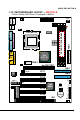
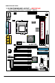
MAGIC-PRO MP-7VIP-A 1-10.1 MOTHERBOARD LAYOUT --- MP-7VIP-A • Default Setting: AMD Athlon ThunderbirdTM 100MHz.
MAGIC-PRO MP-7VIP-A 1-10.2 MOTHERBOARD LAYOUT --- MP-7VIP-AX • Default Setting: AMD Athlon ThunderbirdTM 100MHz.
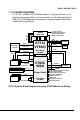
MAGIC-PRO MP-7VIP-A 1-11 CHIPSET DIAGRAM CFWDRST PROCRDY CONNECT • The KT133 / VT8363 and VT82C686A chipset is a high performance, costeffective and energy efficient system controllor for the implementation of AGP / PCI / ISA desktop personal computer system based on 64-bit SocketA (AMD Athlon) processors.
MAGIC-PRO MP-7VIP-A CHAPTER 2 HARDWARE SETUP 2-1 CPU INSTALLATION 1. Pull the lever sideways away from the socket, and then raise the lever up to a 90-degree angle. T KE 462 C SO 2. Take note of the red circle as below picture. While inserting the CPU into the socket, you can find out there is a definite pin orientation for CPU and socket.
MAGIC-PRO MP-7VIP-A 3. Make sure that the CPU position in the socket tightly, and then put the lever down to complete the CPU installation. D AM 62 4 ET CK SO 2-2 AMD SOCKET A (SOCKET 462) PROCESSOR AMD XXXXXXXXXXX XXXXXXXXXXXX XXXXXXX XXXXXXXXX XXXXXXXXXXX XXXX AMD DXX XXX XXXXXXXXXXX XXXXXXXXXXXX XXXXXXX XXXXXXXXX XXXXXXXXXXX XXXX AXX XXX • MP-7VIP-A motherboard works with AMD Athlon Thunderbird TM and DuronTM processor series.
MAGIC-PRO MP-7VIP-A 2-3 CPU FREQUENCY SW1 ON ON PCI CLOCK ON 100MHz (default) 33.3MHz ON 103MHz 34.3MHz ON 105MHz 35.0MHz ON 110MHz 36.7MHz ON 112MHz 37.3MHz ON 115MHz 38.3MHz ON 120MHz 40.0MHz ON 124MHz 31.0MHz ON 133.3MHz 33.3MHz ON 140MHz 35.0MHz ON 150MHz 37.
MAGIC-PRO MP-7VIP-A 2-4 JUMPER DEFINITIONS • The figure below shows the location fo the motherboard’s jumper blocks. CAUTION • Do not move the jumper with the power on. Always trun off the power and unplug the power cord from the computer before changing the jumper. Otherwise, the motherboard could be damaged. FAN1/FAN2: ONBOARD FAN (12V) CPU FAN FAN1 SYSTEM FAN FAN2 Those connectors support processor/system/chassis cooling fan with +12V. Those support three pin head connector.
MAGIC-PRO MP-7VIP-A JP3: FACTORY TEST Only for factory test. JP3 JP4/JP5: VOICE DIAGNOSTIC LANGUAGE SELECT Chinese Language JP4 JP5 English Language (default) JP4 JP5 Japanese Language JP4 JP5 Spanish Language JP4 JP5 1 3 1 1 3 3 1 1 3 3 1 1 3 3 1 3 NOTE: The Voice Diagnosis Technology (JP4, JP5, and JP8) is only supported with MP-7VIP-AX motherboard.
MAGIC-PRO MP-7VIP-A JP10/JP11: VIO SELECT 3.3V (default) JP106 JP11 3.4V JP106 JP11 3.5V JP106 JP11 3.6V JP106 JP11 1 3 1 1 3 3 1 1 3 3 1 1 3 3 1 3 VIO allows you to select the voltage supplied to the DRAM, chipset, AGP, PCI, and the CPU’s I/O buffer. The default voltage (3.3V) should be used unless processor overclocking requires a higher voltage. NOTE! Using a higher voltage may help when overclocking but may result in the shortening of your computer components’s life.
MAGIC-PRO MP-7VIP-A CD_IN1/CD_IN2: CD-ROM AUDIO CONNECTOR PIN NO.
MAGIC-PRO MP-7VIP-A 2-5 CONNECTORS • In this section we list all external connectors that user will use them. 2-5.1 J3 AND J4 J3 1 2 3 4 5 6 7 8 9 10 11 12 13 14 15 J4 HDD LED CONNECTOR PIN PIN PIN PIN 16 26 36 46 DESCRIPTION J3 +5V HDD LED SIGNAL HDD LED SIGNAL +5V This connector supplies power to the cabinet's IDE 6 activity LED. Read and write activity by devices 6 connected to the Primary or SecondaryIDE 6 connector will cause the LED to light up.
MAGIC-PRO MP-7VIP-A J3 1 2 3 4 5 6 7 8 9 10 11 12 13 14 15 J4 ATX POWER SWITCH PIN 126 PIN 136 DESCRIPTION J3 ATX POWER SWITCH GND The system power is controlled by a momentary switch connected to this lead. Pressing the button once will switch the system between ON and SOFT OFF. Pushing the switch while in the ON mode for more 4 seconds will turn the system off. The system power LED shows the status of the system's power.
MAGIC-PRO MP-7VIP-A J3 J4 1 2 3 4 5 6 7 8 9 10 11 12 13 14 15 SPEAKER CONNECTOR PIN PIN PIN PIN 16 26 36 46 DESCRIPTION SPEAKER SIGNAL NONE GND +5V This SPEAKER connector connects to the casemounted speaker. Two sources (LINE OUT and SPEAKER) allow you to hear system beeps and warnings. Only SPEAKER allows you to hear system beeps before the integrated audio has been properly initialized.
MAGIC-PRO MP-7VIP-A J3 J4 1 2 3 4 5 6 7 8 9 10 11 12 13 14 15 SUSPEND LED PIN 146 PIN 156 SUSPEND LED SIGNAL GND DESCRIPTION A1 A2 J3 1 J4 1 B + - - + C D 15 F 15 - + E 20 Connect to Suspend indicator light.
MAGIC-PRO MP-7VIP-A 2-5.2 CHASSIS PANEL CONNECTOR A. B. E. F. C. G. A B C D E F G H I J D. H. I. J.
MAGIC-PRO MP-7VIP-A 2-5.3 ATX POWER SUPPLY CONNECTOR • This connector connects to an ATX power supply. The plug from the power supply only inserts in an orientation because of the different hole sizes. Find the proper orientation and push down firmly making sure that all pins are aligned. • Reminding that your power supply should support at least 10mA on the 5V standby voltage. It may cause an difficulty to power on the system if the power supply can’t support the load.
MAGIC-PRO MP-7VIP-A 2-5.4 SECOND USB CONNECTOR • This motherboard provides 4 sets of USB port. Besides 2 sets of them can be connected directly by USB devices, the others are built-in onboard for user to extend the USB function. • NOTE: User can order the 2nd USB connector from your motherboard dealer and vendor only.
MAGIC-PRO MP-7VIP-A 2-5.
MAGIC-PRO MP-7VIP-A 2-5.
MAGIC-PRO MP-7VIP-A 2-6 VOICE DIAGNOSIS TECHNOLOGY • The Voice Diagnostic Function provides user an indispensable assistance on troublieshooting while assembling your computer components. If there is any conflict or other latent problem triggers a boot-up failure, this new Super-Voice technology will voice you relistically where the conflict/ problem is, then user can remove the malfunction quickly.
MAGIC-PRO MP-7VIP-A Chapter 3 DRIVER INSTALLATION 3-1 VIA AC'97 Audio Controller Driver for Windows 9x 1. Go to CD-ROM driver, we suggest the CD-ROM title is D:\. 2. Find and run D:\MB\VIA\AUDIO\SETUP.EXE 3. Then the setup program will detect your O.S. to install relative files into your system. 4. Reboot your computer.
MAGIC-PRO MP-7VIP-A 3-3 VIA Hardware Monitor Installation Windows95 / Windows98: 1. Go to CD-ROM driver, we suggest the CD-ROM title is D:\. 2. Find and run D:\SUPERCOP\SC3_K7\SETUP.EXE 3. The installation will detect your O.S. to install relative files into your system 4. Reboot the computer. VIA AGP VxD Driver for Windows9x Installation Windows95 / Windows98: 1. Go to CD-ROM driver, we suggest the CD-ROM title is D:\. 2. Find and run D:\MB\VIA\AGP\SETUP.EXE 3.
MAGIC-PRO MP-7VIP-A CHAPTER 4 BIOS SETUP 4-1 INTRODUCE THE BIOS • BIOS stands for Basic Input Output System. It is sometimes called ROM BIOS because it is stored in a Read-Only Memory(ROM) chip on the motherboard. BIOS is the first program to run when you turn on your computer. • BIOS performs the following functions: 1. Initializing and testing hardware in your computer(a process called “POST”, for Power On Self Test). 2. Loading and running your operating system. 3.
MAGIC-PRO MP-7VIP-A lected and configures your computer accordingly. If the battery charge runs too low, the CMOS content will be lost and POST will issue a “CMOS invalid” or “CMOS checksum invalid” message. If this happens, you may have to replace the battery. After the battery is replaced, the proper settings will need to be stored in SETUP. 4-5 WHAT IS POST • POST is an acronym for Power On Self Test.
MAGIC-PRO MP-7VIP-A Create a Boot Floppy (using a DOS system to create the bootable floppy) • Place an unformatted floppy diskette in the floppy drive and format the floppy using the /S option. Example: format a: /s • Alternatively, place a formatted floppy in the floppy drive and use the “sys” command. Example: sys a: Create the BIOS Upgrade Floppy Diskette • Download both the newest BIOS file and AWDFLASH.EXE file via motherboard maker’s website. • The BIOS file you downloaded will be a *.bin format.
MAGIC-PRO MP-7VIP-A • Then appears a program window as below: • After upgraded, the system will reboot itself automatically. • NOTE: You will see a message “CMOS checksum error - Default loaded” during booting the system. Please press to run BIOS program, then reload “LOAD SETUP DEFAULTS” and save this change.
MAGIC-PRO MP-7VIP-A 4-7 CMOS SETUP UTILITY • This VIA KT-133 motherboard comes with the AWARD BIOS from AWARD Software Inc. Enter the Award BIOS program Main Menu by: 1. Turn on or reboot your system. After a series of diagnostic checks, the following message will appear: PRESS TO ENTER SETUP 2. Press the key and the main program screen will appear as follows.
MAGIC-PRO MP-7VIP-A 4-8 STANDARD CMOS SETUP • Standard CMOS Setup allows you to record some basic system hardware configuration and set the system clock and error handling. You only need to modify the configuration values of this option when you change your system hardware configuration or the configuration stored in the CMOS memory gets lost or damaged. Run the STANDARD CMOS SETUP as following: 1.
MAGIC-PRO MP-7VIP-A Date (mm:dd:yy) Set the current date and time. Time (hh:mm:ss) Primary / Secondary This field records the specifications for all non-SCSI Master / Slave hard disk drives installed in your system. Refer to the respective documentation on how to install the drives. Drive A / Drive B Set this field to the type(s) of floppy disk drive(s) installed in your system. The choices are: 360KB, 5.25in., 1.2MB, 5.25in., 720KB, 3.5in., 1.44MB, 3.5in., (default) 2.88MB, 3.5in., None.
MAGIC-PRO MP-7VIP-A 4-9 ADVANCED BIOS FEATURES • ADVANCED BIOS FEATURS allows you to improve your system performance or set up sysem features according to your preference. Run the ADVANCED BIOS FEATURES as following: 1. Choose “ADVANCED BIOS FEATURES” from the Main Menu and a screen with a list of option will appear: 2. Use one of the arrow keys to move between options and modify the selected options by using PgUp / PgDn / + / - keys.
MAGIC-PRO MP-7VIP-A CMOS Setup Utility - Copyright (C) 1984-2000 Award Software Advanced BIOS Features Virus WarningN Disabled CPU Internal CacheN Enabled External CacheN Enabled Item Help Menu Level CPU L2 Cache ECC CheckingN Enabled Quick Power On Self TestN Enabled First Boot DeviceN Floppy Second Boot DeviceN HDD-0 Third Boot DeviceN CDROM Boot Other DeviceN Enabled Swap Floppy DriveN Disabled Boot Up Floppy SeekN Disabled Boot Up NumLock StatusN On Gate A20 OptionN Fast Typema
MAGIC-PRO MP-7VIP-A Virus Warning Enabled: Activates automatically when the system boots up causing a warning message to appear if there is anything attempting to access the boot sector or hard disk partition table. Disabled: No warning message will appear when there is something attempting to access the boot sector or hard disk partition table. NOTE: Many diagnostic (or boot manager) programs which attempt to access the boot sector table can cause the above warning message.
MAGIC-PRO MP-7VIP-A Boot Up NumLock Choose ON (default) or OFF. THis option lets user Status activates the NumLock function at boot-up. Gate A20 Option Choose Normal or Fast (default). This option allows the RAM to access the memory above 1MB by using the fast gate A20 line. Typematic Rate Setting Choose Enabled or Disabled (default). Enable this option to adjust the keystroke repeat rate. Typematic Rate (Chars Range between 6 (default) and 30 characters per / Sec) second.
MAGIC-PRO MP-7VIP-A 4-10 ADVANCED CHIPSET FEATURES • ADVANCED CHIPSET FEATURES allows you to change the values of chipset registers. These registers control the system options. Run the ADVANCED CHIPSET FEATURES as following: 1. Choose “ADVANCED CHIPSET FEATURES” from the Main Menu and a screen with a list of option will appear: 2. Use one of the arrow keys to move between options and modify the selected options by using PgUp / PgDn / + / - keys.
MAGIC-PRO MP-7VIP-A CMOS Setup Utility - Copyright (C) 1984-2000 Award SoftwareN Advanced Chipset Features Bank 0/1 DRAM TimingN Bank 2/3 DRAM TimingN Bank 4/5 DRAM TimingN SDRAM Cycle LengthN DRAM ClockN DRAM Drive StrengthN DRAM Drive ValueN Memory HoleN PCI Master Pipeline ReqN P2C/C2P ConcurrencyN Fast R-W Turn AroundN System BIOS CacheableN Video RAM CacheableN AGP Aperture SizeN AGP Driving ControlN AGP Driving ValueN AGP Fast WriteN K7 CLK_CTL SelectN OnChip USBN OnChip USB 2N USB Keyboard SupportN
MAGIC-PRO MP-7VIP-A Bank 0/1 2/3 4/5 DRAM This item allows you to select the value in this field, Timing depending on whether the board has paged DRAMs or EDO (Extended Data Output) DRAMs. The choice: EDO 50ns, EDO 60ns, Slow, Medium, Fast, Turbo. SDRAM Cycle Length You can select CAS latency time in HCLKs of 2/2 or TIme 3/3. The system board designer should have set the values in this field, depending on the DRAM installed.
MAGIC-PRO MP-7VIP-A System BIOS Choose Enabled or Disabled (default). When enabled, Cacheable the access to the system BIOS ROM addressed at F0000H - FFFFFH is cached. Video RAM Cacheable Choose Enabled or Disabled (default). When enabled, the access to the VGA RAM addressed is cached. AGP Aperture Size Choose 4, 8, 16, 32, 64 (default), 128 or 256 MB. Memory mapped and graphics data structures can reside in a Graphics Aperture. This area is like a linear buffer.
MAGIC-PRO MP-7VIP-A OnChip Sound Enabled (default): Turn on AC’97 codec chip controller. Disabled: Turn off AC’97 codec chip controller or user can plug external add-on sound card. OnChip Modem Enabled: Turn on MC99 feature. Disabled (default): Turn off AC’97 codec chip controller or user can connect external add-on modem. IDE HDD Block Mode Choose Enabled (default) or Disabled. If your hard disk size is larger than 540MB, then choose Enabled.
MAGIC-PRO MP-7VIP-A Memory Parity/ECC This item enabled to detect the memory parity and Check Error Checking & Correcting. The choice: Enabled, Disabled. CPU Voltage Regulator This item allows user to adjust the CPU Vcore voltage. The instant damage of CPU is due to the wrong Vcore voltage setting, so that we recommend that user should leave this item with Default setting unless you know how to adjust it. The choice: Default, -0.05V, -0.10V, +0.40V, +0.30V, +0.20V, +0.10V, +0.05V. 3.
MAGIC-PRO MP-7VIP-A 4-11 INTEGRATED PERIPHERALS • INTEGRATED PERIPHERALS option allows you to get some informations inside your system when it is working. Run the INTEGRATED PERIPHERALS as following: 1.
MAGIC-PRO MP-7VIP-A 2. Use one of the arrow keys to move between options and modify the selected options by using PgUp / PgDn / + / - keys. An explanation of the keys follows: : “Help” gives oions available for each item. + : Change color. : Get the previous values. These values are the values with which the user started in the current session. : Load all options with the BIOS default values. : Load all options with the Setup default values.
MAGIC-PRO MP-7VIP-A On-Chip Primary/ The chipset contains a PCI IDE interface with supSecondary PCI IDE port from two IDE channels. Select Enabled to activate the first and/or the second IDE interface. Select Disabled to deactivate an interface if you install a primary and/or second add-on IDE interface. The choice: Enabled (default), Disabled. IDE Prefetch Mode The onboard IDE drive interfaces supports IDE prefetching for faster drive accesses.
MAGIC-PRO MP-7VIP-A Onboard FDC Select Enabled if your system has a floppy drive conController troller (FDC) installed on the system board and you want to use it. If you install add-in FDC or the system has no floppy drive, select Disabled in this field. The choice: Enabled, Disabled. Onboard Serial Select an address and corresponding interrupt for the Port 1 / Port2 first and second serial ports. The choice: 3F8/IRQ4, 2E8/IRQ3, 3E8/IRQ4, 2F8/ IRQ3, Disabled, Auto.
MAGIC-PRO MP-7VIP-A Parallel Port EPP Type Select EPP port type 1.7 or 1.9 The choice: EPP1.7, 1.9. Onboard Legacy Audio This field controls the onboard audio. • Sound Blaster • SB I/O Base Address • SB IRQ Select • SB DMA Select • MPU-401 • MPU-401 I/O Address • Game Port (200-207H) 3. Press to return to the Main Menu when you finish setting up all items.
MAGIC-PRO MP-7VIP-A 4-12 POWER MANAGEMENT SETUP • POWER MANAGEMENT SETUP allows you to set the system’s power saving functions. Run the POWER MANAGEMENT SETUP as following: 1.
MAGIC-PRO MP-7VIP-A ACPI Function Enabled: Turn on ACPI function. Disabled (default): Turn off ACPI function. • Press on the Power Management item, then there is a list of it appears for you to choose further setting.
MAGIC-PRO MP-7VIP-A ACPI Suspend Type This item will allow you to select the ACPI suspend type. You can select S3(STR) for suspending to DRAM or S1(POS) for power on suspend under Windows 98 ACPI mode. The choice: S1(POS), S3(STR). PM Control by APM When enabled, an Advanced Power Management device will be activated to enhance the Max. Power Saving mode and stop the CPU internal clock, If Advanced Power Management (APM) is installed on your system, selecting Yes gives better power savings. If the Max.
MAGIC-PRO MP-7VIP-A Soft-Off by PWRBTN Instant-Off (default): Turn off the system poer at once after pushing the power button. Delay 4 Sec: Turn off the system power 4 seconds after pushing the power button. (to meet PC97/98 spec) • Press on the Wake Up Events item, then there is a list of it appears for you to choose further setting.
MAGIC-PRO MP-7VIP-A Wake Up On LAN/Ring An input signal on the serial Ring Indicator (RI) line (in other words, an incoming call on the modem) awakens the system from a soft off state. The choice: Enabled, Disabled. RTC Alarm Resume When Enabled, you can set the data and time at the which the RTC (Real Time Clock) alarm awakens the system from suspend mode. The choice: Disabled (default), Enabled. Date (of Month) Set a certain date when RTC Alarm Resume option is Enabled to awaken the system.
MAGIC-PRO MP-7VIP-A The following is a list of IRQ’s (Interrupt ReQuests), which can be exempted much as the COM ports and LPT ports above can. When an I/O device wants to gain the attention of the operating system, it signals this by causing an IRQ to occur. When the operating system is ready to respond to the request, it interrupts itself and performs the service. When set On, activity will neither prevent the system from going into a power management mode nor awaken it.
MAGIC-PRO MP-7VIP-A 4-13 PNP / PCI CONFIGURATION • PNP/PCI CONFIGURATION allows you to set the system’s power saving functions. Run the PNP/PCI CONFIGURATION as following: 1.
MAGIC-PRO MP-7VIP-A PNP OS Installed Yes: OS supports Plug and Play function. No (default): OS doesn’t support Plug and Play function. NOTE: BIOS will automatically disable all PnP resources except the boot device card when you select Yes on Non-PnP operating system. Reset Configuration Choose Enabled or Disabled (default). Disabled reData tains PnP configuration data in BIOS and Enabled resets the PnP configuration data in BIOS. Resource Controlled Choose Manual (default) or Auto.
MAGIC-PRO MP-7VIP-A DMA Resources Press Enter. Please refer to the below list.
MAGIC-PRO MP-7VIP-A 4-14 PC HEALTH STATUS • This section helps you to get more information about your system including CPU temperature, FAN speed and voltage. It is recommended that you contact with your motherboard supplier to get proper value about your setting of the CPU temperature. CMOS Setup Utility - Copyright (C) 1984-2000 Award Software PC Health Status Current Current Current Current VcoreN 2.5VN 3.3VN 5VN 12VN CPU Temp.N System Temp.
MAGIC-PRO MP-7VIP-A 4-15 FREQUENCY/VOLTAGE CONTROL CMOS Setup Utility - Copyright (C) 1984-2000 Award Software Frequency Control Auto Detect DIMM/PCI ClkN Spread Spectrum ModulatedN CPU Host Clock (CPU/PCI)N Method In Linear Funct.N CPU HOST By Linear Funct.
MAGIC-PRO MP-7VIP-A 4-16 LOAD FAIL-SAFE DEFAULTS • When you press on this item you get a confirmation dialog box with a message similar to: “ Load Fail-Safe Defaults (Y / N) ? N ” Pressing “Y” loads the BIOS default values for the most stable, minimalperformance system operations.
MAGIC-PRO MP-7VIP-A 4-18 SET SUPERVISOR / USER PASSWORD • These two options allow you to set your sysem passwords. Normally, the supervisor has a higher ability to change the CMOS setup option than the user. The way to set up the passwords for both Supervisor and User are as follows: 1. Choose “Change Password” in the Main Menu and press . The following message appears: “Enter Password : “ 2. The first time you run this option, enter your password up to 8 characters and press .
MAGIC-PRO MP-7VIP-A 4-19 SAVE & EXIT SETUP • SAVE & EXIT SETUP allows you to save all modifications you have specified into the CMOS memory. Highlight this option on the Main Menu and the following message appears: “SAVE to CMOS and EXIT (Y/N) ? Y “ Press key to save the configuration changes. 4-20 EXIT WITHOUT SAVING • EXIT WITHOUT SAVING option allows you to exit the Setup Utility without saving the modifications that you have specified.