MAGICAR M871A Car alarm with two-way remote Installation guide 1
MAGICAR M871A Car alarm with two-way remote Installation guide 2
TABLE OF CONTENTS I. INTRODUCTION............................................................................................................................4 II. PLACING........................................................................................................................................4 III. ADDITIONAL RELAY 12V CONNECTION..............................................................................5 IV. WIRING ARRANGEMENT .................................................................
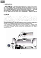
EN I. INTRODUCTION MAGICAR M871A is a safety device with the highest level of security. Thanks to the 2way remote with pager you will be immediately informed about possible car intrusion, as well as the manner of the intrusion even though you are too far from the car to hear the siren. The biggest advance of the two-way remote control is a possibility to use without direct view of the car. All the commands you will send will be confirmed by remote.
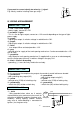
EN WARNING! ¾ When installing a door contact, you must find an appropriate wire from the wire bundle of a car (it is important from the security point of view as well as that of remote starting) ¾ Wiring used for the alarm connection must not be broken nor its insulation damaged. This should prevent wiring from short-circuit. ¾ After the installation completed, you have to test the alarm according to the user’s manual.
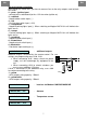
+12V 86 If you want to connect shortly two wires by (-) signal. E.g.: Mostly used for installing alarm gas relays. 87 85 impuls (-) line A 87a 30 line B IV. WIRING ARRANGEMENT CONNECTOR 1 – CN1 1 – red - +12V Power supply - power supply, connect to +12V. 2 –red/white – Lights - This is a line for lights output, connect on +12V or earth depending on the type of lights power supply. 3 – purple - Signal lights output. It switches voltage in red/white wire CN1. 4 – purple - Signal lights output.
EN EN Starter-blocking connection: After cutting car starter lines, you have to connect lines to the relay outputs used to block the starter. 2 – green - Ignition Input - connect to the switchboard (to the +12V wire when ignition on). 3 – red/black - Negative door switch input ( - ) 4 – red - Positive door switch input (+12V) 5 – orange/black - Negative parking lights input (-). When switching on Magicar M871A this will indicate the lights are on. 6 – orange - Positive parking lights input (+).
- LED indication CONNECTOR 9 - white - RPS sensor CONNECTOR 10 - red - Shock sensor 1 – black - Grounding 2 – white - Shock sensor input – second level (-) CONNECTOR 11 - green - 3 – red - Power supply of +12 V 4 – yellow - Shock sensor input – first level (-) Additional sensor 1 – black - Grounding – In case of turning the alarm or the additional sensors off, the grounding is disconnected which means the sensor is mains operated.
EN Note: • If you want to carry out any other changes, start the whole process over again. • If you hear a long beep, you are out of programming menu area. Start again by the step 1. Failure notice: If the remote happened to be out of the range when programming changes, it will display „FAIL“ notice and the programming will be cancelled. Programming menu No. 1 When the door is open and ignition is on keep buttons I and II pressed simultaneously for 2 sec. Options No.
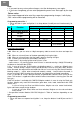
EN No. Function 2-01 2-02 2-03 2-06 2-08 2-09 Trunk output time Door lock impulse Door unlock impulse Parking lights AUX 1 AUX 2 Shock sensor on/off during AUX output Arm/disarm by OEM remote control 2-11 2-13 Options Button II Button III Button I Button IV 0.5 sec 0.8 sec 0.8 sec Normal mode 0.5 sec 0.5 sec 2 sec 4 sec 4 sec Continuous mode 5 sec 5 sec 3 sec 2 x 0.8 sec 2 x 0.
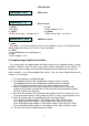
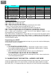
EN and the pulse mode (Mode 2). Mode 1 – continuous Mode 2 – pulse Output - Lights Lights - flashing Lights Control Unit Hazard Lights Switch Light output (CN1-3 or 4) Common input (CN1-2) Relay contact bypassing the hazard light switch Fig.1 Parking Lights output connected to the Hazard switch Calibration In case of using the mode 1 or 2 it is required to set the time of output closure.
Entering valet mode with PIN code. 1. Armed. 2. By opening the door, the alarm will be triggered. Siren will chirp. 3. Within 3 sec turn the ignition on/off three times. 4. Lights will flash once. 5. Push the button on RPS as many times, as your first number is. Intervals between the click/pushes must not be longer than 1.5 sec. 6. Lights will flash once. 7. Push the button on RPS as many times, as your second number is. 8. Lights will flash twice. Siren is off. Valet mode is activated.
EN EN Programming of security code (1111-9999): 1. Ignition on. 2. Open the door. 3. Push the button on RPS sensor 10 times. At every single click, LED will flash red once. Intervals between the click/pushes must not be longer than 1.5 sec. 4. Blue LED will start flashing rapidly. If it does not happen, go back to step 1. 5. Push the button on RPS as many times as your first number between 1-9 is. After each push red LED will flash. 6.
Fig.4 Original built-in central power lock Fig.3 Original built-in central power lock & using compressor to control the switch. Note: Active time 4 sec. CN2 Unlock Lock green/black green green/white Air-compressor Main line Electric motor switch yellow yellow/white NC1 COM1 NO1 NC2 COM2 NO2 Contact - locked yellow/black Contact - unlocked NO1 NC2 COM2 NO2 Locked COM1 Unlocked NC1 Ground CN2 yellow/black yellow yellow/white green/black green green/white Original built-in control unit.
EN Wiring diagram Magicar M871A Lock (NO) Lock (COM) Lock(NC) Unlock (NO) Unlock (COM) Unlock (NC) Wiring diagram door lock system Page 39 6 green/white 5 green 4 green/black 3 yellow/white 2 yellow 1 yellow/black fuse 15A fuse 15A Output to Starter kill (-250mA) Ignition input Door trigger input (-) Door trigger input (+) 1 violet 2 green 3 red/black 4 red Parking light input (-) Parking light input (+) 5 orange/black 6 orange Trunk trigger input (-) Hood trigger input (-) 7 gray/black 8 brown/b
- The car alarm system is designed for fitting into all kinds of cars with petrol and diesel engines with +12V volatge finished by a negative pole. Car alarm must be fitted following manufacturer‘s recommendation. The alarm installation to be carried out only by authorised service centre. Consult the choice of the service sentre with a manufacturer. International approval marks and/or international certificates of conformity are attached onto the cover of system main parts as well as onto the box.