
Operation Manual
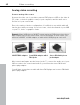
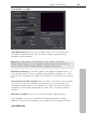
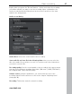
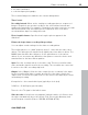
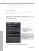
Table Of Contents
- Copyright
- Preface
- Support
- Uninstalling the program
- Serial Number
- Introduction
- Quick Start
- Workspaces
- Settings
- Video recording
- Objects
- Markers
- Multi-cam editing
- Title
- Effects
- Apply effects to objects
- Video effects in the Media Pool
- Movement effects in the Media Pool
- Stereo3D in the Media Pool
- Audio effects in the Media Pool
- Design elements in the Media Pool
- Personalized templates in the Media Pool
- Effects masks (Plus/Premium version)
- Additional effects
- Animate effects
- Attach to picture position in the video
- Image stabilization
- Image improvements for the entire movie
- Image improvements for individual objects
- Audio editing
- Stereo3D (Plus/Premium version)
- Special functions and wizards
- Video recorder
- Burning
- Export
- Managing video projects
- Menus
- File Menu
- Edit Menu
- Undo
- Redo
- Cut objects
- Copying objects
- Paste objects
- Duplicate objects
- Delete items
- Select all objects
- Save objects as takes
- Cut
- Musical editing
- Range
- Form group
- Ungroup objects
- Wizards
- Mixdown Audio
- Audio and video mixdown
- Start preview rendering...
- Remove range(s) for preview rendering...
- Edit snap point
- Marker
- Move screen view
- Multicam
- Menu effects
- Windows menu
- "Share" menu
- Tasks menu
- Help Menu
- Help
- Content
- Context help
- Quickstart/Recording/Editing/Burning and exporting tutorial video
- Ask questions online in the Knowledge Community
- Find knowledge & workshops
- Online tutorials
- Get in contact with other users
- About MAGIX Movie Edit Pro MX
- Register online
- Online Update
- Download video effects plug-ins
- Display Tool Tips
- Reset Program Settings to Default...
- Context menu (right click)
- Keyboard shortcuts
- Problems and solutions
- Integrated browser
- Activate codecs
- Annex: Digital Video and Data Storage
- MPEG-4 encoder settings
- Appendix: MPEG Encoder Settings
- MPEG glossary
- Glossary
- If you still have questions
- More about MAGIX
- Index

Video recording 89
www.magix.com
for video surveillance
or in time-lapse photography
The recorded images are added to the current arrangement.
Time Control
Recording interval: When active, starting recording produces a sequence of
images. Snapshots are saved according to the selected time interval and
numbered sequentially. For example, if snapshots are taken every two seconds
and then inserted every five frames into the slideshow, then a ten times
accelerated time lapse recording will result.
Photo length in frames: Specifies how long the photos appear in the
slideshow.
Enhanced single-frame recording dialog settings
You can adjust certain settings for the video recording driver.
These dialog boxes, so-called "property sheets", come with the video card
drivers. The driver-specific features may slightly vary from driver to driver. The
MAGIX team has little direct influence on the performance of the various
drivers. If you encounter any difficulties, then please contact the video card
manufacturer for the latest driver updates.
Input: Sets the crossbar switch of the video card. This lets you define what
video and audio signal is used in the recording. The crossbars are connected
in series to the video recording chip itself.
Output: In the "Output" field, the video output (for the crossbars) is the input
for the recording chip (video or audio decoder in) of the video card. In the
"Input" field, you select the signal source to be used for this input by the video
card during recording.
Composite in = the normal video input (typically a cinch jack)
S-VHS in = S-VHS input (special cable)
Tuner in = the TV signal of the built-in tuner
Video decoder: If the picture only appears in black & white or it flickers, then
the video standard may be set incorrectly. PAL_B is used in Germany and
most European countries (France: SECAM; US/CAN: NTSC).