MDR 24 24/96 QUICK START GUIDE 24 TRACK/24 BIT, DIGITAL AUDIO HARD DISK RECORDER
MDR 24/96 CAUTION AVIS RISK OF ELECTRIC SHOCK DO NOT OPEN RISQUE DE CHOC ELECTRIQUE NE PAS OUVRIR CAUTION: TO REDUCE THE RISK OF ELECTRIC SHOCK DO NOT REMOVE COVER (OR BACK) NO USER-SERVICEABLE PARTS INSIDE REFER SERVICING TO QUALIFIED PERSONNEL ATTENTION: POUR EVITER LES RISQUES DE CHOC ELECTRIQUE, NE PAS ENLEVER LE COUVERCLE. AUCUN ENTRETIEN DE PIECES INTERIEURES PAR L’USAGER. CONFIER L’ENTRETIEN AU PERSONNEL QUALIFIE.
Introduction ----------------------------4 Appendix A: Compatible Cables ----39 Save your Box! -------------------------------How To Use This Guide --------------------Conventions ---------------------------------About “Tape” --------------------------------Overview -------------------------------------- 4 4 5 5 6 Analog and Digital Multitrack Cables ----39 Other Cables---------------------------------- 40 Troubleshooting and service --------42 Notes-------------------------------------43 Setup & Config
MDR 24/96 Introduction Save your Box! Uncle Jeff’s Bottom Ten Reasons to Save the Box: 10. You think boxes grow on trees? 9. It’s actually a time capsule, packed with a biological code that can’t be decrypted until 2043. 8. Its festive graphics will cheer up those other boxes forgotten in your attic. 7. Impress your friends: tape it up and pretend that you actually have two MDR24/96s. 6. If you throw it away, bad people will know you have a studio in your house. 5.
The MDR24/96 Quick Start Guide uses the following conventions to help you find information quickly: Text Conventions a) File or folder names (example: C:\HDR Projects\Ode To Masters\Ode To Masters.hdr) b) Software or hardware controls (example: Punch) c) Proper names of objects in GUI or front/rear panel (example: Transport) Icons This icon identifies in-depth explanations of features and practical tips.
MDR 24/96 Overview By combining traditional multitrack tape recording features with the power and flexibility of hard disk recording, the Mackie Designs MDR24/96 takes multitrack recording to a level never before achieved by a product in its price range. In addition to the standard battery of traditional tape-based features, the MDR24/96: • Combines the familiarity of a multitrack tape machine with the security of non-destructive recording and non-degrading recording media.
This chapter explains how to set up and configure the MDR24/96 for use in your studio. Two application examples show how to interface the MDR24/96 with analog and digital recording consoles. Required Equipment Of course, there’s more to a studio than a recorder and some musicians. At a minimum, you’ll need the following to make the MDR24/96 feel at home: • 3 Mackie 8-channel I/O (input/output) cards.
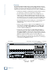
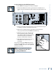
While the MDR24/96 ships with AIO•8 cards already installed, three other flavors of I/O cards are also available. All I/O cards can be mixed and matched in any combination. AIO•8 ANALOG I/O OUTPUT AIO•8 DIO•8 APOGEE DIGITAL I/O TDIF INPUT MDR 24/96 I/O Cards & Cables • Each AIO•8 provides 8 analog line-level inputs and outputs on two 25-pin D-subminiature (DB25) connectors. These connectors are pin-for-pin compatible with the analog (not TDIF) DB25 connectors found on the TASCAM DTRS recorders.
1. If the MDR24/96 is plugged into AC power, unplug it. 2. Unscrew the thumbscrews at the top and bottom of each I/O card to be removed. Grasp one thumbscrew with each hand and gently pull the card out. OUTPUT OUTPUT OUTPUT ANALOG I/O ANALOG I/O ANALOG I/O INPUT INPUT INPUT M Quick Start Guide To replace the AIO-8 cards with different I/O cards: TAPE IN/OUTS 3. Before you take I/O cards from their bags, touch a grounded metal object to discharge any static electricity from your body. 4.
NOT MDR 24/96 WARNING Sync Card & Cables - Word Clock and Digital Synchronization The Sync Card provides ports to synchronize the MDR24/96’s sample clock and time/transport position to other equipment. The functions of the jacks and switch, from top to bottom are: • SMPTE Input / Output – This 1/4” TRS jack serves as an input when slaved to incoming SMPTE time code, and as an output when generating SMPTE time code to synchronize other devices with the MDR24/96.
TDIF (DIO•8) With the MDR24/96 as a master, connect Word Clock Out of the MDR24/96 to Word Clock In on the receiving device(s). If connecting to older TASCAM DTRS recorders, use the Sync Out port on the first DIO•8 card instead of Word Clock Out. If there is more than one DTRS recorder in the chain, connect Sync Out to the word clock input of the first DTRS recorder only; the other recorders are synchronized through their interconnecting DTRS cables.
MDR 24/96 Mackie Media (Optional) The MDR24/96 emulates the tape library tradition with Mackie Media M•90 and Mackie Media PROJECT drives. Both drives come complete with a plug-in tray for quick removal and a nifty storage case for shelving and transporting the drives. Trays can be purchased separately if you want to use your own UDMA IDE drives. The MDR24/96 can record or play directly off the M•90 so you can change sessions as quickly as changing tape on a 24-track – no backup time required.
Note: The Remotes duplicate nearly all of the front panel operating controls. When we describe a front panel operation, you’ll probably find it available on the Remote also. If you have a Remote, try it both ways. If you don’t have a Remote yet, think of how convenient it would be. Installing either remote is as simple as plugging in a telephone.
MDR 24/96 Configuration Before starting a Project, you will need to configure the MDR24/96 I/O card options and synchronization parameters. These parameters determine where the sample clock is coming from, how fast the sample clock runs, and how many bits are recorded in every sample. Some options, like sample rate and bit depth, will become “standards” that you won’t need to change very often.
The PDI•8 card options include sample rate conversion for each stereo AES/EBU input, and status bit control (pro/consumer mode) for each output. When a PDI•8 card is first installed, its default settings are for sample rate conversion Off, and channel status bits set to indicate the Pro (AES/EBU) format. In most circumstances you won’t need to change these settings.
MDR 24/96 Synchronization Sample Clock The PDI·8 is the only Mackie I/O card that currently supports 88.2 or 96 kHz operation. Do not operate the MDR24/96 at these Sample Rates with AIO·8, DIO·8, or OPT·8 cards installed. See Errata for more information The Sample Clock setting determines the source of the MDR24/96 sample clock. If the MDR24/96 is a clock master or is not connected to any other digital device(s), set it to Internal. If the MDR24/96 is a word clock slave, set it to Word Clock.
1. Move to the last page of the Sync Options menu with the Page Right (>) button. Select SR/2 In. 2. Set the Word Clock Input divisor to On or Off using the (–)Dec / (+)Inc or << / >> buttons. Off selects 1x operation, On selects 0.5x operation. 3. Select OK, then Select SR/2 Out and set the Word Clock Output divisor to On or Off. <- SYNC OPTIONS Video Field SR/2 In [4] SR/2 Out SAMPLE RATE/2 OUT << ON >> OK 4. Select OK and press the Sync button to exit the menu.
MDR 24/96 Hookups This section shows how the MDR24/96 is typically connected to both analog and digital consoles (using the Mackie Analog and Digital 8•Bus consoles as examples). These examples assume that the rest of your studio equipment (monitors, sound sources, outboard processing, etc.) is already connected, or that you know how to connect it.
MDR24/96 Settings 1. Set the Sample Clock to Internal. 2. Set the Sample Rate and Bit Depth according to your preference. Console Settings Set the 24•8 console to the nominal +4 dBu operating level by setting the five Operating Level switches in the Sub Out and Tape Return sections to the ‘out’ position. This example describes the hookup for the D8B console equipped for analog I/O.
MDR 24/96 TDIF Hookup (DIO•8) Cables & Hardware (3) DIO•8 cards for MDR24/96 (3) DIO•8 cards for D8B (1) Clock I/O card for D8B (3) TDIF cables (1) 75 Ω BNC word clock cable Hookup 1. Connect the three TDIF cables between the corresponding TDIF jacks on the MDR24/96 and D8B. 2. When TDIF is used, the D8B must have a Clock I/O card installed. To make the D8B the clock master, connect its Word Clock Out (not DIO•8 Sync out) to the MDR24/96 Word Clock In.
Quick Start Guide TDIF Hookup with DIO•8 Apogee Clock I/O Card DIO•8 Cards APOGEE DIGITAL I/O APOGEE DIGITAL I/O APOGEE DIGITAL I/O TDIF TDIF TDIF TDIF Connection Word Clock Out Word Clock Out APOGEE SYNC OUT TDIF Cables (DB25) SYNC IN OUT IN ADAT OPTICAL SYNC TDIF APOGEE DIGITAL I/O TDIF OUT ADAT OPTICAL APOGEE DIGITAL I/O TDIF Use one only Depress the Termination button if the MDR24/96 is set to Slave IN APOGEE DIGITAL I/O MDR 24/96 OUT IN DIO•8 Cards SYNC OUT ADAT OPTICAL
MDR 24/96 ADAT Optical Hookup (DIO•8 or OPT•8) Cables & Hardware (3) DIO•8 or OPT•8 cards for MDR24/96 (3) DIO•8 or OPT•8 cards for D8B (1) Clock I/O card for D8B (6) ADAT Optical cables (1) 75Ω BNC word clock cable Hookup 1. Connect three ADAT Optical cables from the MDR24/96 Optical Outputs to the Optical Inputs on the corresponding D8B I/O cards. 2. Connect three ADAT Optical cables from the MDR24/96 Optical Inputs to the Optical Outputs on the corresponding D8B I/O cards. 3.
Quick Start Guide ADAT Optical Hookup with DIO•8 Apogee Clock I/O Card DIO•8 Cards APOGEE DIGITAL I/O APOGEE DIGITAL I/O TDIF TDIF TDIF APOGEE DIGITAL I/O Word Clock Out Word Clock Out APOGEE SYNC ADAT Optical Out APOGEE Digital 8 Bus OUT SYNC IN OUT IN ADAT OPTICAL SYNC TDIF APOGEE DIGITAL I/O TDIF OUT ADAT OPTICAL APOGEE DIGITAL I/O TDIF Use one only Depress the Termination button if the MDR24/96 is set to Slave IN APOGEE DIGITAL I/O OUT IN OUT IN ADAT OPTICAL OUT ADAT OPTI
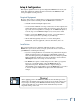
MDR 24/96 ADAT Optical Hookup with OPT•8 OPT•8 Cards Apogee Clock I/O Card APOGEE SYNC ADAT Optical Out Word Clock Out Word Clock Out APOGEE Digital•8 Bus Word Clock In Word Clock Out (MDR24/96 as Master) WARNING NOT Word Clock Out (D8B as Master) Word Clock In ADAT Optical In MDR Sync Card ADAT Optical Out Use one only MDR 24/96 Depress the Termination button if the MDR24/96 is set to Slave ADAT Optical In Word Clock In OPT•8 Cards Word Clock Out Figure 3 24 MDR 24/96
Cables & Hardware (3) PDI•8 cards for MDR24/96 (3) PDI•8 cards for D8B (1) Clock I/O card for D8B (3) DB25 to DB25 AES/EBU snakes (1) 75Ω BNC word clock cable Hookup 1. Connect the three AES/EBU cables between the corresponding AES/EBU connectors on the MDR24/96 and D8B. Note: Determining which unit in Figure 4 provides master clock depends on your application. For information on advanced applications, see the Technical Reference manual. 2.
MDR 24/96 AES/EBU Hookup with PDI•8 PDI•8 I/O Cards Apogee Clock I/O Card APOGEE SYNC PDI•8 PDI•8 PDI•8 Word Clock Out Word Clock Out Word Clock In AES/EBU I/O AES/EBU I/O Word Clock In APOGEE AES/EBU I/O Digital 8•Bus AES/EBU Cables (DB25) NOT MDR Sync Card PDI•8 PDI•8 PDI•8 MDR 24/96 Use one only AES/EBU I/O Depress the Termination button if the MDR24/96 is set to Slave AES/EBU I/O WARNING Word Clock Out (D8B as Master) AES/EBU I/O Word Clock Out (MDR24/96 as Master) Word Cloc
Now that you’ve finished installing and configuring the MDR24/96, you’re almost ready to start your first Project. We still want you to read this entire guide, but we already hear some of you shuffling and muttering. Okay, okay, okay... for the terminally impatient, read this chapter, then you can go out and play with your friends. Note: The front panel display blanks after several minutes of being idle. Pressing any button below the display will turn it back on.
MDR 24/96 Basic Transport Operations The MDR24/96 transport and recording controls are similar to those on most multitrack tape recorders. Play Play puts the MDR24/96 into play from any state (as if you didn’t know). Play also punches out of record and cancels master record standby while leaving the Transport in play. To put the Transport into play: ♦ Press Play. REWIND FAST FWD STOP PLAY RECORD Fast Wind Rewind and Fast Forward put the MDR24/96 into fast wind mode from any state.
Locate points provide fast access to frequently used locations in your Project. The MDR24/96 has two numbered Locates (two additional numbered Locates are availible when using the Remote 24 or Remote 48). Storing a Locate point saves the Current Time (Transport position) to the Locate button. Recalling a Locate causes the Transport to jump to the stored time. To recall a Locate point: ♦ Press Loc 1 or Loc 2 to jump to that point.
MDR 24/96 Track Editing The MDR24/96 features non-destructive Cut, Copy, and Paste editing. Edit operations are performed on an "Area" defined by the range of time between the Start and End points on selected track(s). Edit operations are remembered in a 999-level History List so that every edit can be undone and redone. To perform an edit: 1. First press the Track/Edit button, then the button of the desired edit operation. The Record Ready LEDs change to indicate which Tracks are selected.
Undo Current Command Undo / Redo Undo and Redo allow you to step forward and backwards through your editing changes. The History List number lets you keep track of your changes so that you can easily do A/B comparisons of different edits.
MDR 24/96 5. When you’ve completed the Project name, select New to create the Project and exit. PROJECT: PLAYLIST: DRIVE: AVAIL: Project#1 Playlist 1 C:Internal 01:35:00 Your new project is now open; the Active Drive, Project Name, and Playlist Name are shown in the LCD display and in the GUI above the Current Time display. In the MDR24/96 and HDR24/96, Playlists are that part of a Project that keeps track of all of your recording and editing, and controls what you hear when you hit Play.
A professional analog recorder has meters that indicate 0 VU at a +4 dBu nominal signal level. Generally you can record peaks 10 to 15 dB above that before distortion becomes objectionable. This 10-15 dB range above the nominal level is called “headroom”. The overload indicators on the MDR24/96 light when the signal level reaches –1 dBFS. On digital recorder meters, zero represents the full-scale digital signal level, 0 dBFS for short.
MDR 24/96 4. After adjusting the tape output levels for each console channel, follow your console manufacturer’s instructions for setting the console tape return levels. With analog I/O, a +22 dBu signal at the dBu equivalent MDR24/96 inputs and outputs corresponds to +22 dBu OL 0 dBFS inside the MDR24/96. So, if your 2 +20 4 +18 console has a nominal output level (0 VU) of 7 +15 +4 dBu, there is 18 dB of headroom before 10 +12 15 +7 you hit the maximum record level on the 20 +2 25 –3 MDR24/96.
Using a footswitch with the MDR24/96 gives you hands-free access to two of the most-used MDR24/96 functions. The footswitch is extremely handy when you want to use your hands for other tasks, like playing your instrument, working the console, or eating pizza. Punch punches in just like pressing Play+Record and punches out like pressing Play. When playing, hitting the footswitch punches in on all armed tracks.
MDR 24/96 Delete Last With the MDR24/96 you don’t need to worry about filling up your hard disks with unwanted takes. The Delete Last function permanently erases all the audio files recorded during the last record pass. A recording pass consists of all punches made within one play/stop cycle. If you make edits after doing a record pass, Delete Last will have no effect. To delete the last recording pass: ♦ Press the Delete Last button.
With Mackie Media drives, you can back up your Projects on removable media that you can hand to the client or store in your tape library. Backing up and restoring Projects is as simple as copying the Projects between the internal and the Mackie Media drives. To copy Projects between the internal and Mackie Media drives: 1. Press the Backup button. BACKUP SOURCE: Internal DESTINATION: External Set Source Dest Exit Backup 2.
MDR 24/96 To format and verify media performance from the MDR24/96: 1. Press the Disk Util button. DISK UTILITY MENU 2. Now select Format. The LCD screen will display a message asking you to verify the drive speed for recording and playback. Mount Format Verify 3. Select OK. When the format operation has completed, another message will appear asking you to verify the drive speed for recording and playback. 4. If a UDMA drive is installed, select OK.
Analog and Digital Multitrack Cables The following companies supply analog and digital multitrack cables for use with the MDR24/96 I/O cards: Horizon Music, Inc. P.O. Box 1988, Cape Girardeau MO 63702-1988 Tel: (800) 255-9822; Fax: (800) 455-3460 http://www.horizonmusic.
MDR 24/96 Marshall Electronics PO Box 2027, Culver City, CA 90231 Tel: (800) 800-6608; Fax: (310) 391-8926 http://www.mars-cam.com/cable.html AIO•8 Analog Interface Cables DC-DAXM Series DB25 to 8 male XLR’s DC-DAXF Series DB25 to 8 female XLR’s DC-DAS Series DB25 to 8 1/4” TRS connectors Standard lengths: 3, 5, 10, 15, 20, 25 feet DIO•8 TDIF Interface Cables DCD-88D Series DB25 to DB25. Standard lengths: 1, 3, 6, 12, 15, 20, 25, 33 feet.
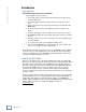
REC 2 REC 1 ON POWER 2 50 50 1 30 35 40 30 35 40 3 REC 3 10 15 10 15 20 25 10 15 20 25 7 7 50 30 35 40 20 25 2 4 2 4 7 OL OL 2 4 4 REC 4 50 30 35 40 20 25 10 15 7 2 4 OL 5 REC 5 50 30 35 40 20 25 10 15 7 2 4 OL 6 REC 6 50 30 35 40 20 25 10 15 7 2 4 OL 7 REC 7 50 30 35 40 20 25 10 15 7 2 4 OL 8 REC 8 50 30 35 40 20 25 10 15 7 2 4 OL 9 REC 9 50 30 35 40 20 25 10 15 7 2 4 OL 10 REC 10 50 30 35 40 20 25 10 15 7 2 4
MDR 24/96 Troubleshooting and service Although you probably won’t need them, troubleshooting tips can be found in the Technical Reference Manual. Technical support is available by contacting your Mackie dealer, calling Mackie Designs at (800) 258-6883 (8:00 AM to 5:00 PM Pacific Time), or visiting Mackie’s website at www.mackie.com. Please read the included warranty information, then complete and return the included Warranty Registration card, or it’s straight to bed for you with no dinner.
__________________________________________________________________________________________________________ __________________________________________________________________________________________________________ __________________________________________________________________________________________________________ __________________________________________________________________________________________________________ ____________________________________________________________________________________