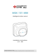
MSK-101-MM Intelligent motion sensor Installation instructions v1.7 - EN Carefully read this manual in its entirety. You will find useful information to take full advantage of the product's potential, use it safely and obtain the best results.
Copyright © 2017-2018, Inxpect SpA All rights reserved in all countries. Any distribution, alteration, translation or reproduction, partial or total, of this document is strictly prohibited unless with prior authorization in writing from Inxpect SpA, with the exception of the following actions: l l l Printing the document in its original format, totally or partially. Transferring the document on websites or other electronic systems.
Contents Get to know MSK-101-MM MSK-101-MM Applications Barrier configuration Field of vision Interferences Installation and use Before installation Install and configure the sensor Appendix Technical data Disposal Conformity and restrictions Service and warranty Download Useful conventions for requesting assistance Perforated base dimensions MSK-101-MM | Installation instructions v1.7 OCT 2018 | msk-101-mm_instructions_en_us v1.
Instruction updates Publication date OCT 2018 Code Updates msk-101-mm_instructions_en_ Modified United Kingdom and France national restrictions us v1.
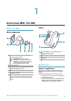
1 Get to know MSK-101-MM MSK-101-MM Sensor Main components Part Description A Perforated housing base for adaptation to the main junction boxes B C D E F IMPORTANT: the base of the container is, together with the two fastening screws (not provided), an integral part of the sensor antiremoval and anti-tear system.
Get to know MSK-101-MM Examples of volumetric sensor installation Indoor wall installation. Outdoor installation. Examples of barrier sensor installation Indoor ceiling installation. Indoor wall installation. 6 MSK-101-MM | Installation instructions v1.7 OCT 2018 | msk-101-mm_instructions_en_us v1.
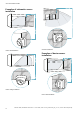
Get to know MSK-101-MM Indoor ceiling installation. Outdoor installation with adapter. Barrier configuration Adapter for barrier assembly Barrier installation for protection of a wall or window requires the sensor to be installed at approximately 15 cm (5.9 in) from the same wall. If other adequate supports are not available, an adapter is necessary for assembling the barrier (product code: MSK-101-BM. Example of installation without adapter. Indoor hallway installation.
Get to know MSK-101-MM Example of installation with MSK-101-BM adapter. Sensor direction The MSK-101-BM adapter, according to the installation method, allows directing the sensor to the left or the right. Side view. Range of the field with vertical sensor direction (barrier) Sensor directed towards the left. Top view. Sensor directed towards the right. Field of vision Side view. Range of the field with horizontal sensor direction (volumetric) Calculation of the field of vision Top view.
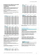
Get to know MSK-101-MM Examples of the field of vision with horizontal sensor direction (volumetric) NOTICE: the detection start and end values do not guarantee detection of a standing person. The reported values may slightly vary based on the installation conditions. Note: only some heights are reported, but every intermediate value is allowed and guarantees optimum performance. The dimensions of the field of vision expressed in meters and feet are as follows. h (m) α (°) s1 (m) s2 (m) s3 (m) 1 1.
Get to know MSK-101-MM Interfering materials Below is a list of materials that could impact the sensor performance if they hide it: l l l l l l l l surfaces having metal-based paints or carbon-based paints tinted windows surfaces having EMI/RFI glasses or mirrors surfaces with water pipes, cables tiles having metal-based glaze including blue cobalt metal screen foil foil-backed insulation materials (e.g. foil) foil moist materials (e.g.
2 Installation and use Before installation Install MSK-101-MM 1. Assemble the sensor: Necessary components and tools l l Wi-Fi dongle (product code: WSYNC-RJWIFI or WSYNC-RJ-WIFI-US). Android or iOS device with Wi-Fi enabled and the Inxpect Security application installed (see "MSK-101-MM" on page 5). IMPORTANT: to ensure correct functioning, allow all requested permissions for the application.
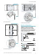
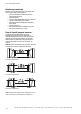
Installation and use Install and configure the sensor 4. Fasten the sensor housing to the base. Assemble the sensor 1. Using the prepared holes, fasten the base to the wall or to the junction box with two screws (not provided). See "Perforated base dimensions" on page 21. Assemble the sensor with the MSK-101-BM adapter (sensor directed to the right) 2. Extract the sensor from the adjustable support. 3. Pass the cable with the wires coming out of the alarm control unit into the sensor housing. 12 1.
Installation and use 3. Extract the sensor from the adjustable support. Assemble the sensor with the MSK-101-BM adapter (sensor directed to the left) 1. Using the prepared holes, direct the base of the sensor as shown in the figure and fasten it to the wall or to the junction box with two screws (not provided). See "Perforated base dimensions" on page 21. 4. Pass the cable into the sensor housing. 2.
Installation and use 4. Turn the base 180°. 8. Assemble the sensor housing to the adapter. 5. Tighten the screws. Connect the sensor to the alarm control unit 1. Remove the sheath and the hose by at least 5 cm (2 in). 6. Extract the sensor from the adjustable support. 2. Connect the power supply and relay outputs. It is recommended to connect relay 3 (tampering) and 4 (fault) to a 24 h line from the alarm control unit. 7. Pass the cable into the sensor housing.
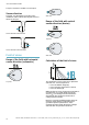
Installation and use Direct the sensor 4. Tilt down the adjustable support to reach the desired sensor inclination. 1. Insert the sensor into the adjustable support, leaving the connector in sight. Connect the dongle and configure the sensor 1. Insert the dongle into its caddy. 2. Turn the sensor to lock it into the adjustable support. 3. Turn the adjustable support to orient the sensor direction vertically (barrier application) or horizontally (volumetric application).
Installation and use 2. Connect the dongle and fasten it to the sensor. For 45° sensor inclinations downwards, see "45° downward inclination" below. It can be fastened to the right or left of the sensor. Fasten the sensor 1. Tighten the screws to fasten the adjustable support. Check in the application that the adjustable support has not moved. 2. Disconnect the dongle. Hold the adjustable support firmly and completely insert the sensor. 3. Use the Inxpect Security application to configure the sensor. 3.
Installation and use 4. Fasten the body of the sensor to the base using the provided screw. 5. Insert the provided caps. MSK-101-MM | Installation instructions v1.7 OCT 2018 | msk-101-mm_instructions_en_us v1.
3 Appendix Technical data Note *: the device has been designed to be supplied by an external power supply unit for alarm systems, internally protected by a short-circuit. General specifications Note**: the instructions presented in this manual are sufficient for meeting the requirements of standard UL639. Installations not consistent with these instructions could also comply with the standard. Detection method Frequency Inxpect motion detection motor based on FMCW radar Working band: 24–24.
Appendix Conformity and restrictions Service and warranty Declaration of conformity and certifications Customer service The manufacturer, Inxpect SpA, declares that the type of radio equipment MSK-101-MM complies with the directive 2014/53/EU. The full EU declaration of conformity text is available on the company's website at the address www.inxpect.com. At the same address all updated certifications are available for download.
Appendix Useful conventions for requesting assistance Conventions Some useful conventions to communicate with Inxpect SpA technical assistance are provided below. Type of application Spatial direction Legend Icon Description Wall installation Ceiling installation 20 MSK-101-MM | Installation instructions v1.7 OCT 2018 | msk-101-mm_instructions_en_us v1.
Appendix Perforated base dimensions MSK-101-MM | Installation instructions v1.7 OCT 2018 | msk-101-mm_instructions_en_us v1.
Exclusive distributor for North America: MAGNASPHERE Corp. N14 W23777 Stone Ridge Dr., Suite 160, Waukesha, WI 53188 www.magnasphere.com info@magnasphere.com (262) 347-0711 MSK-101-MM Installation instructions v1.7 OCT 2018 msk-101-mm_instructions_en_us v1.7 Copyright © 2017-2018 Inxpect SpA Manufacturer: Inxpect SpA Via del Serpente, 91 25131 Brescia (BS) Italy www.inxpect.com security@inxpect.