Installation / Operation Manual CinemaVision Resonance Technology, Inc. 18121 Parthenia Street Northridge, California 91325, USA +1 (818) 882-1997 +1 (800) 428-MRTV www.mrivideo.com Innovative MRI-Compatible Entertainment Systems Advanced Functional MRI Systems Resonance Technology, Inc.
Notice: This document contains proprietary information protected by copyright. All rights reserved. No part of the document may be photocopied or reproduced without the prior written consent of Resonance Technology, Inc. Information contained in this document is covered by one or more of the following U.S. patents: 5627902, 5877732, 5432544, 5412419. Resonance Technology, Inc.
Table of Contents 1. Introduction ......................................................................................... 1 2. Safety Information............................................................................... 2 2.1. Important Warnings for Patient and Operator Safety ................................................................ 2 2.2. Precautionary Patient Conditions................................................................................................ 2 2.3.
Resonance Technology, Inc.
1 Introduction 1. Introduction Congratulations on your purchase of the CinemaVision system for patient comfort. This device represents more than 40 years of development and state-of-the-art engineering. We are confident this product will give you the tools you need for comforting the patient while undergoing MRI scans. This installation/operation manual outlines how to properly install and operate the system. Thank you for choosing to purchase this system from Resonance Technology, Inc.
2 Safety Information 2. Safety Information At Resonance Technology, Inc., patient safety is our top priority. Please review this section completely as its contents are vital to the safety of the installer, the clinician/operator, and the patient. 2.1. Important Warnings for Patient and Operator Safety WARNING Prior to every use, inspect all system components that come in contact with the patient. Discontinue product usage immediately if any damage is evident or presents other potential hazards.
2 Safety Information Loud Sound Volume Avoid using audio headset with high volume for the patient as hearing expert’s advice against continuous loud and extended audio play. If the patient experiences a ringing in their ears, reduce the audio headset volume. The patient is advised to consult their health doctor for further advice. 2.3.
2 Safety Information 2.5. General Warnings for Electronic Products Electric shock Failure to observe all operating and maintenance instructions may cause damage to this product and may result in property damage and/or injury or death from electric shock, fire, or other cause. To avoid the risk of electric shock or fire hazard, a multi-outlet power strip or extension cord should not be connected to the video monitor socket outlet on the CinemaVision controller.
2 Safety Information 2.7. Medical Device Safety Approvals The CinemaVision System has the following safety certifications: Page 5 Resonance Technology, Inc.
3 Installation Materials 3. Installation Materials Your CinemaVision system comes complete with all the necessary components to complete the system installation at your facility.
3 Installation Materials The following list shows the rooms where the items are to be installed.
4 Room Layout Overview for Installation 4. Room Layout Overview for Installation WARNING: Absolutely no ferromagnetic tools should be brought inside the MRI Suite! While no tools, other than tie wraps, are required to install the system in the MRI suite, absolutely all ferromagnetic tools remain outside of, and away from the door leading to, the MRI suite. Below is a typical MRI setup.
4 Room Layout Overview for Installation Magnet Room Control Room LCD Video Monitor Audio Headset Video Goggles Tech Remote Patient Monitoring Camera Control Room Camera A/V Console (Optional) Penetration Panel Wave Guide 8-channel Fiber Optic Cable (50m / 150’) Transducer Transducer Power Cable Transducer Power Cable (15m / 50’) (3m / 10’) Transducer Power Supply Must be placed outside the magnet’s 20-Gauss line Page 9 Resonance Technology, Inc.
5 Installation Procedure 5. Installation Procedure The installation procedure consists of four major phases: • Installing the MR Laser Link Cable and Transducer Power Supply Cables • Magnet Room Component Interconnection • Equipment Room Component Interconnection • Control Room Component Interconnection Before you begin the installation, determine the location where the transducer will be installed. It should be a secure area next to the magnet and away from traffic.
5 Installation Procedure 5.1. Installing the MR Laser Link Cable and Transducer Power Supply Cables The preferred method of routing the fiber optic cable is to run the cable from the control room through the overhead ceiling drop tiles and down into the computer room in front of the filter panel through the Fiber Optics Waveguide. It can then be run alongside the other MRI cables going to the magnet. The cable should end where you intend to locate the transducer.
5 Installation Procedure 5.2. Magnet Room Component Interconnection 5.2.1. Remove both upper and lower cable covers from the transducer. 5.2.2. Unravel all the fiber optic cables from the plastic coil. Select the red (#1), green (#2), blue (#3), black (#4), and brown (#5) connectors. Put the unused fibers back into the plastic coil. Remove the plastic dust caps from the five selected fiber optic connectors. Keep the dust caps for future use whenever cables might be removed for service. 5.2.3.
5 Installation Procedure 5.2.4. Secure the fiber optic bundle strain relief to the transducer housing. Make sure all of the individual fiber optic cables have a smooth bend radius. The fiber optics can be damaged if bent too tightly. Fold the protective tape over the fiber optic cables. Rubber grommet used to secure the fiber optics bundle Put the spare unused fiber cables back in the plastic coil. Protective tape 5.2.5. Connect the Power Supply cable to the Transducer.
5 Installation Procedure 5.2.7.1. Use the included non-magnetic screws to attach the patient camera to the back wall behind the magnet. WARNING: Never use any metal screws that might be attracted by the magnet as they may become projectiles and cause serious injury or death to anyone inside the magnet room. Remember that the magnetic field is always present. 5.2.7.2. Connect the 4-pin camera power/signal cable to the camera, and route the cable to the transducer.
5 Installation Procedure 5.3. Equipment Room Component Interconnection 5.3.1. Place the Transducer power supply into the location chosen in Step 5.1.4. This location must be outside of the 20-Gauss line. 5.3.2. Connect the round transducer power cable connector to the power supply. Make sure the ring on the connector is secure. 5.3.3. Make sure the power supply’s switch is set to the “OFF” position.
5 Installation Procedure The photo below shows an overview of the CinemaVision A/V Console rear panel. 5.4.1. Unravel all the fiber optic cables from the plastic coil. Select the red (#1), green (#2), blue (#3), black (#4), and brown (#5) connectors. Put the unused fibers back into the plastic coil. Remove the plastic dust caps from the five selected fiber optic connectors. Keep the dust caps for future use whenever cables might be removed for service. 5.4.2.
5 Installation Procedure 5.4.3. Connect the S-video and composite video (RCA) cables from the VIDEO MONITOR section to the LCD monitor. 5.4.4. Connect the monitor power supply to the LCD monitor and to the VIDEO MONITOR AC OUT connector. 5.4.5. Connect the Tech Remote Control to the TECH REMOTE connector. 5.4.6. Connect the Control Room Camera to the CONTROL ROOM CAMERA connector. Please note the connector only fits one way. The rib on the connector points to the left. 5.4.7.
5 Installation Procedure 5.4.12. Use the included plastic tie wraps to secure all cables connected to the back of the CinemaVision Controller to prevent accidental disconnection. 5.4.13. Install the rear cable cover once all functions are verified to be working. Page 18 Resonance Technology, Inc.
Page 19 Resonance Technology, Inc.
6 Operation 6. Operation Below is a description of the CinemaVision control room components. The Controller converts the selected audio and video source signals into optical signals that the MR Laser Link cables route to the Transducer unit inside the magnet room. The Transducer unit recreates the signals and routes the audio and video signals to the audio headset and video goggles. LCD Video Monitor to view the selected video source.
6 Operation 6.2. Front Panel Controls AUXILIARY VIDEO INPUTS OPERATION: In order to use the Auxiliary Video Inputs in the CinemaVision system proceed as follows: • Select the desired auxiliary video input for the patient/technologist using the front panel buttons or the Tech Remote Control. • Depending on the selected kind of video input source (S-video/Composite), select the specific Auxiliary video input using the Tech Remote Control wheel #4 (rightmost wheel).
6 Operation 6.3. Technologist Remote Control Wheel #1 - Controls the patient headset audio level. Scrolling the wheel up increases the headset volume. Scrolling the wheel down decreases the headset volume. Scrolling the wheel down while pressing down on the Menu wheel (#4) mutes the headset. Scrolling the wheel up while pressing down on the Menu wheel (#4) un-mutes the headset. (Previous volume setting is resumed.) Wheel #2 - Controls the Patient Microphone audio level.
6 Operation The Tech Remote Control system functions are as follows: Menu Functions Option Patient A/V DVD* AUX Camera TV Radio DVD* Aux Camera TV Radio Control Room AV DVD Control (if DVD is the selected source for Patient or Control Room) TV Channel (if TV is the selected source for Patient or Control Room) Radio Station FM Tuner (if Radio is the selected source for Patient or Control Room) Radio Station AM Tuner (if Radio is the selected source for Patient or Control Room) Aux Input (if AUX is
6 Operation 6.4. Optional Patient Monitor Camera Setup Patient Camera Controls: The patient camera model MRI/2020 comes with automatic Iris control and manually adjusted Focus and Zoom controls. Adjusting the Focus lens control: When adjusting the focus for the camera lens, rotate the control to get the best picture clarity. Adjusting the Zoom lens control: The Zoom control is used to magnify the specific target the lens is focused on. You may have to re-adjust the focus when changing this setting.
6 Operation 6.5. Patient Setup 6.5.1. Overview Make sure all cables have been connected securely to the Transducer in the Magnet Room and that the system components do not impede any walkways. Ensure that the Transducer is not placed directly in front of the bore of the magnet. Before placing the Video Goggles and Headphones on the patient, make sure that the microphone audio levels on the Control Room Tech Remote Control have been set to a comfortable level.
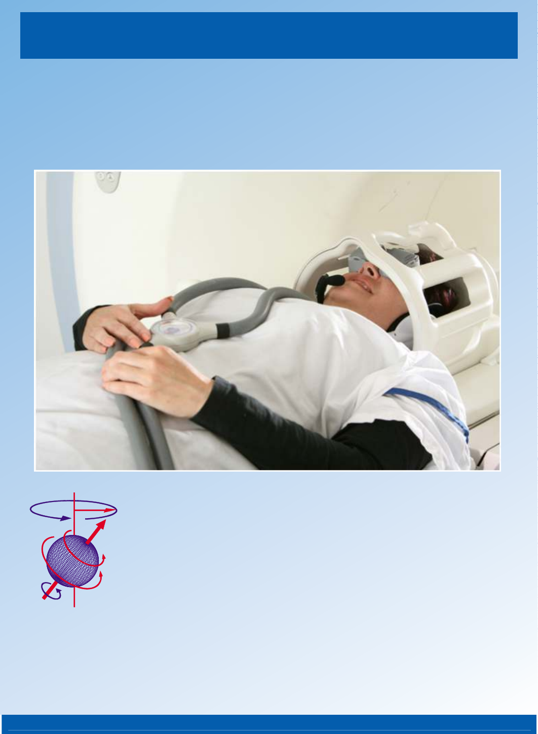
6 Operation 6.5.4. How to fit the Video Goggles into the 8-channel head coil 6.5.4.1. With the patient’s head half-way in the 8-channel head coil, slide the Video Goggles under the center part. Slide the Video Goggles under the Head coil center part 6.5.4.2. Fit the patient’s head all the way into the coil and slide the Video Goggles down to fit the patient’s eyes. Place the patient’s head all the way into the 8-channel head coil 6.6.
Page 27 Resonance Technology, Inc.
7 Troubleshooting 7. Troubleshooting If the problem arises inside the Magnet Room area: NOTE: Turn off the Transducer Power Supply to prevent damage to the system components, when plugging in or unplugging the power supply cable, headset, and/or video goggles.
7 Problem No communication from the Headset. Headset Microphone and Patient Alert not working. Troubleshooting Diagnosis Green fiber optic connection might be disconnected or broken Visual Details No color on the Logo (above) Tech Remote message (below) Headset not functioning properly. No audio and microphone not working on Headset Blue fiber optic connection might be disconnected or broken No color on the Logo. Left middle light is Red.
7 Troubleshooting Problem Patient camera (located in MRI) no streaming video feed to CinemaVision Controller Diagnosis Red fiber optic connection might be disconnected or broken Visual Details The Transducer indications will look normal Patient not receiving Audio or Video. The Transducer not staying on or working intermittently The Transducer can be going out of sync* with the controller.
Page 31 Resonance Technology, Inc.
8 Specifications 8.
8 Specifications Below is the Medical Device Safety Test Certificate for the CinemaVision System: Page 33 Resonance Technology, Inc.
9 Support Information 9. Support Information If you have any questions regarding the CinemaVision system use or installation, please don’t hesitate to call Resonance Technology, Inc. Customer Service Department. Service and technical support staff may be reached Monday through Friday 8 A.M. to 5 P.M., Pacific Standard Time (USA) at +1 (818) 882-1997, or e-mail to support@mrivideo.com. Page 34 Resonance Technology, Inc.
9 Support Information Resonance Technology, Inc. Product Recycling Program: Resonance Technology Inc. actively supports the protection of the environment by efficiently recycling all our electronic products. Our everyday pollution prevention activities reduce the need for electronic waste to go into landfills. At Resonance Technology Inc. we are committed to our customers, our communities and to everyone's environment. In light of the above, Resonance Technology, Inc.
Notes Page 36 Resonance Technology, Inc.