
Specifications


5
Installation Procedure
Page 17
Resonance Technology, Inc. CinemaVision System Installation / Operation Manual: RTC-CV Rev 14
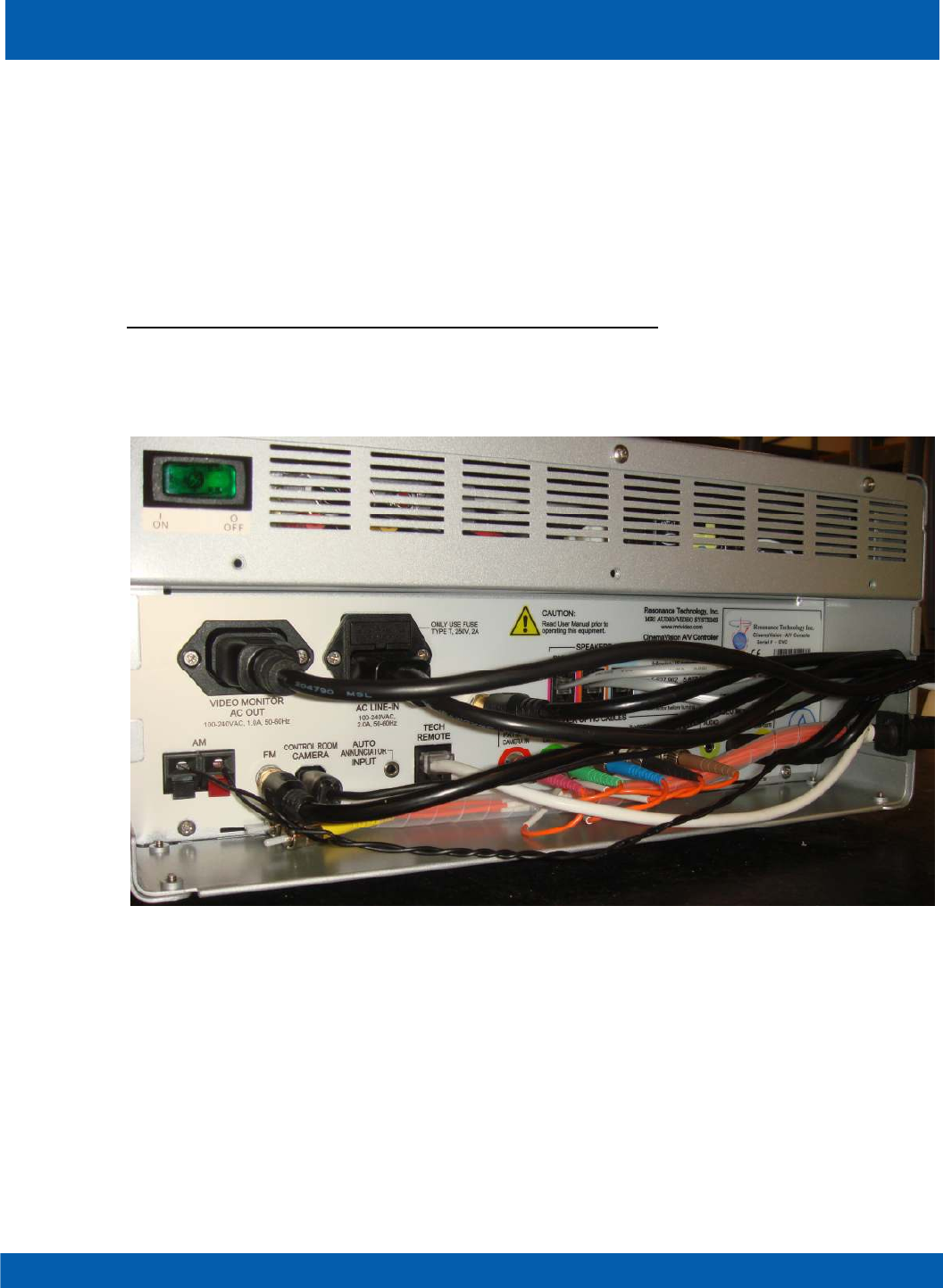
5.4.3. Connect the S-video and composite video (RCA) cables from the VIDEO MONITOR section to the LCD
monitor.
5.4.4. Connect the monitor power supply to the LCD monitor and to the VIDEO MONITOR AC OUT
connector.
5.4.5. Connect the Tech Remote Control to the TECH REMOTE connector.
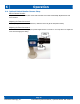
5.4.6. Connect the Control Room Camera to the CONTROL ROOM CAMERA connector. Please note the
connector only fits one way. The rib on the connector points to the left.
5.4.7. Connect the Audio Speaker cables.
5.4.8. Make sure the Controller power switch is in the off position. Connect the Hospital Grade
Power Cord to the Controller and an available active AC power outlet.
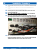
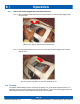
5.4.9. Insert the strain relief of the fiber optic cable into the square notch in the side panel, using the side
which is the most convenient for the layout of the desk area. Place the other cables into the round
notches, using the side which is the most convenient. The photo below shows a typical arrangement.
5.4.10. Power on the LCD Monitor and then power on the Controller.
5.4.11. Power on the Transducer Power Supply, usually located in the computer room. (Exact location will
vary depending on installation and magnet type.) The logo rings on the CinemaVision Controller and
Transducer should start rotating within 30 seconds of both units being powered up.