
Owner's manual


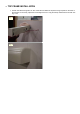
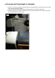

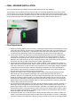
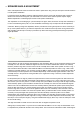
Table Of Contents
- MMC 2 INSTALLATION INSTRUCTION MANUAL
- TABLE OF CONTENTS:
- SELECTION OF SPEAKER LOCATION
- PAINTING SPEAKER FRAMES
- TIPS FROM THE PROS FOR DO-IT-YOURSELFERS
- WALL PREPARATION
- TOP FRAME INSTALLATION
- ATTACHING BOTTOM FRAME TO SPEAKER
- BOTTOM FRAME ATTACHMENT TO WALL
- FINAL SPEAKER INSTALLATION
- Final Adjustments
- HOOKUP
- In case you missed it in the manual-
- SPEAKER ANGLE ADJUSTMENT
- Phasing
- Bass Management and Processor Settings
- Tweeter Level Control

C. TIPS FROM THE PROS FOR DO-IT-YOURSELFERS
1. To run a speaker wire into a wall and out another hole at the bottom, insert a fine steel chain in the top hole
that is the length needed to reach the junction box. Use a magnet at the junction box to locate the steel chain.
The steel chain will be used to pull the speaker wires through the wall.
2. In some cases, it is not practical to route the wires in the wall. A hide-a-cord channel can be used to route the
motor wires on the wall down to the lower frame. When the speakers are closed, the hide-a-cord strip is not
visible. From the bottom frame to the baseboard, the easiest options are flat speaker wire which can be
painted or hide-a-cord channels. Note, the hide-a-cord channels must be low profile to allow the MMC 2 to
close completely.
3. For the motor and speaker wires to have clearance between the top and bottom frames and the wall, it is
necessary to route a small groove on the back of frames.
4. A low voltage junction box at the baseboard or a convenient location, is highly recommended.
WALL PREPARATION
1. Position the hardboard template against the wall approx. 26" from the floor where the speaker is to be
located. Locate the speaker between studs whenever possible. Mark the wall using the upper right corner
hole of the template. Set the template aside.
2. Drill a 1/4" dia. hole in that location.
3. Hold the template against the wall and insert a 1/4" dia. dowel in the hole, leaving 1/4" exposed. See Fig. 1.
4. Level the template by placing a level on the top or side of the template. See Fig. 2. CAUTION- Take great
care to ensure that the wall is plumb (vertical) and the template is level before drilling the holes. The
speakers will not close or open if severely out of plum or level. As an additional precaution, tape the
template into position once the template is level--and recheck the level. Misaligned holes are a SERIOUS
problem and will require starting over with the installation in a different location.
5. Drill a 1/4" dia. hole in the upper left corner of the template. Insert a 1/4" dia. dowel in this hole. Maintaining
the template in a level position, drill a second hole in the bottom MIDDLE hole and install a dowel. Now, the
template will hang unassisted.
6. CAUTION- Double-check to be sure that the template is level. The 4 corner holes are hyper-critical. Once
they are drilled, there is very little adjustment that can be done to correct misalignment of the motor mounts.
The center top and bottom holes are access holes and are not critical to proper alignment.
7. Install (4) sheet rock anchors in the outermost (4) holes. Center holes are for wire feed only. Plastic sheet
rock anchors are provided with the speakers. If these are used, the 1/4 inch hole must be enlarged to 5/16
inch. Insert the plastic sheet rock anchors flush with the wall.
8. Install (4) #8 x 1-1/2" screws into the sheet rock anchors with approximately 3/16 inch clearance from the
wall. USE HAND TOOLS ONLY. NO POWER TOOLS!
9. Install painter's tape on the wall above the location of the top frame to prevent marring of the wall while
installing the top frame.
Fig. 1