
Owner's manual
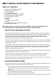

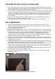

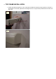
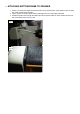

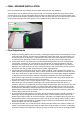
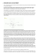
Table Of Contents
- MMC 2 INSTALLATION INSTRUCTION MANUAL
- TABLE OF CONTENTS:
- SELECTION OF SPEAKER LOCATION
- PAINTING SPEAKER FRAMES
- TIPS FROM THE PROS FOR DO-IT-YOURSELFERS
- WALL PREPARATION
- TOP FRAME INSTALLATION
- ATTACHING BOTTOM FRAME TO SPEAKER
- BOTTOM FRAME ATTACHMENT TO WALL
- FINAL SPEAKER INSTALLATION
- Final Adjustments
- HOOKUP
- In case you missed it in the manual-
- SPEAKER ANGLE ADJUSTMENT
- Phasing
- Bass Management and Processor Settings
- Tweeter Level Control

G. FINAL SPEAKER INSTALLATION
Many of the adjustments and installation are much easier with the aid of an LED headlamp.
The final step is the most difficult (and may require the help of an assistant). Slightly raise the top frame to allow
clearance for the pin on the top of the speaker wheel to clear the top frame when it will be moved into position. See
Fig. 10. Slide the motor assembly (and drive wheel) back with your thumb (See Fig. 10) to allow clearance between
the two wheels so that the shaft on the speaker can be inserted into the top frame pivot hole. See Fig. 10.
H. Final Adjustments
1. Helpful hint--Ensuring that the panel moves freely or detecting the slight resistance of the Cam/Stop is made
easier if the motor assembly and drive wheel is pulled away from the idler wheel. The motor assembly can
be held out of the way by attaching a 1 inch-wide piece of duct tape to the entire length of the motor frame.
Pull the frame back with the tape under tension and attach the duct tape to the end of the wood frame.
2. The top frame must be snug to the wall to prevent accidental dislodging of the top frame. Readjust the top
screw heights, if necessary, for a snug fit into the key holes. Before you begin the adjustment, take the
precaution of securing the top frame. It will be necessary to lift up on the speaker frame as you make this
adjustment. This could result in the top frame coming loose from the wall. Painter's tape can help to prevent
the top frame from being pushed upward during the speaker angle adjustment.
3. If the top frame were inadvertently knocked off, the speaker could fall, causing damage to the speaker. To
install a keeper to prevent this accident, make a mark on the wall at the top of the frame on both ends of the
frame. Drill a small hole in the wall the same size as a brad (which has a small head). When the installation
is complete. Insert the brads into the holes after completing the installation. The head of the brad will be
above the line of sight and will act as a keeper to prevent the top frame from being pushed upward. Use a
long nose priers to remove the brad for servicing the speakers.
4. Important- The wheels must be properly aligned for FULL contact to ensure that the wheels will not slip
during opening or closing. Adjust the wheel height on the speaker with the included allen wrench, if
necessary. The help of an assistant will be required to adjust the wheel height. Raise the top frame and, with
the help of an assistant, hold the speaker in a vertical position while loosening the set screws to make the
height adjustment. Reinstall the shaft into the top frame pivot hole while pulling back the motor assembly to
allow for wheel clearance. Slide the loosened wheel up or down on the shaft to have maximum contact with
the drive wheel. Tighten the two set screws.
5. To confirm that the speaker panel can move freely, pull the drive motor assembly back with your thumb so
that the drive wheel is disengaged from the idler wheel. Slowly move the speaker panel through it's 180
degree range of motion to check for excessive resistance. If the MMC 2 is installed correctly for plumb and
level (so that the motor is not pushing the panel "uphill" upon opening or closing), and the speaker panel is
free to move without undue resistance, our testing and field experience has shown that the motor and drive
wheels will reliably open and close the MMC 2.
6. The template provides very accurate placement of the top and bottom frame holes. However, mistakes can
happen. In the event the gap between the top or bottom frame and the speaker is not correct, a modification
is possible to allow for some adjustment of the gap spacing. The frame key hole slot can be lengthened with
Fig. 10