Flex 8EX System Radio Control Equipment Instruction Manual 0-TC-FLEX8E R4 December 2013 © Copyright 2013 Magnetek Material Handling
Service Information Your New Radio System Thank you for your purchase of Magnetek’s Enrange™ Flex EX radio remote control system. Without a doubt, our Flex EX system is the ultimate solution for providing precise, undeterred, and safe control of your material. If your product ever needs modification or service, please contact one of our representatives at the following locations: U.S. Service Information For questions regarding service or technical information contact: +1.866.MAG.SERV +1.866.624.
PRODUCT MANUAL SAFETY INFORMATION Magnetek, Inc. (Magnetek) offers a broad range of radio remote control products, control products and adjustable frequency drives, and industrial braking systems for material handling applications. This manual has been prepared by Magnetek to provide information and recommendations for the installation, use, operation and service of Magnetek’s material handling products and systems (Magnetek Products).
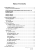
Table of Contents 1. INTRODUCTION ....................................................................................................................................... 6 2. RADIO CONTROLLED SAFETY .............................................................................................................. 7 2.1 CRITICAL INSTALLATION CONSIDERATIONS ................................................................................ 8 2.2 GENERAL ................................................................
6. RECEIVER INSTALLATION .................................................................................................................... 35 6.1 OUTPUT RELAY CONTACT DIAGRAM........................................................................................... 35 6.2 PRE-INSTALLATION PRECAUTIONS ............................................................................................. 36 6.3 STEP-BY-STEP INSTALLATION ................................................................................
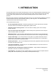
1. INTRODUCTION The Flex radio remote control systems are designed for control of industrial equipment and machinery such as overhead traveling cranes, jib cranes, gantry cranes, tower cranes, electric hoists, winches, monorails, conveyor belts, mining equipment and other material handling equipment where wireless control is preferred. Each Flex system consists of a transmitter handset and receiver unit.
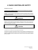
2. RADIO CONTROLLED SAFETY WARNINGS and CAUTIONS Throughout this document WARNING and CAUTION statements have been deliberately placed to highlight items critical to the protection of personnel and equipment. WARNING – A warning highlights an essential operating or maintenance procedure, practice, etc. which if not strictly observed, could result in injury or death of personnel, or long term physical hazards.
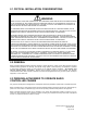
2.1 CRITICAL INSTALLATION CONSIDERATIONS WARNING PRIOR TO INSTALLATION AND OPERATION OF THIS EQUIPMENT, READ AND DEVELOP AN UNDERSTANDING OF THE CONTENTS OF THIS MANUAL AND THE OPERATION MANUAL OF THE EQUIPMENT OR DEVICE TO WHICH THIS EQUIPMENT WILL BE INTERFACED. FAILURE TO FOLLOW THIS WARNING COULD RESULT IN SERIOUS INJURY OR DEATH AND DAMAGE TO EQUIPMENT.
2.4 SAFETY INFORMATION AND RECOMMENDED TRAINING FOR RADIO CONTROLLED EQUIPMENT OPERATORS Anyone being trained to operate radio controlled equipment should possess as a minimum the following knowledge and skills before using the radio controlled equipment.
operate a crane, hoist or lifting device if the chain or wire rope is not seated properly in the sprockets, drum or sheave operate any damaged or malfunctioning crane, hoist, lifting device or other material handling equipment change any settings or controls without authorization and proper training remove or obscure any warning or safety labels or tags leave any load unattended while lifted leave power on the radio controlled equipment when the equipment is not in operation opera
2.7 BATTERIES WARNING KNOW AND FOLLOW PROPER BATTERY HANDLING, CHARGING AND DISPOSAL PROCEDURES. IMPROPER BATTERY PROCEDURES CAN CAUSE BATTERIES TO EXPLODE OR DO OTHER SERIOUS DAMAGE. FAILURE TO FOLLOW THIS WARNING COULD RESULT IN SERIOUS INJURY OR DEATH AND DAMAGE TO EQUIPMENT. 2.8 BATTERY HANDLING Use only batteries approved by Magnetek for the specific product. Do not dispose of a battery pack in fire; it may explode. Do not attempt to open the battery pack. Do not short circuit the battery.
2.11 SPECIFIC SYSTEM WARNINGS Below are some specific operating safety tips that should be strictly followed when operating a Flex 8EX System: 1. Check the Status LED on the transmitter for any signs of low battery power (refer to page 41). 2. Check the Status LED on the transmitter for any signs of irregularities (refer to page 41). 3. Make sure the system is not set to the same channel as any other Flex systems in use within a distance of 300 meters (900 feet). 4.
3. GENERAL SYSTEM INFORMATION 3.1 TRANSMITTER HANDSET 3.1.1 External Illustration (Standard Push Button Configuration) (Fig. 01) 1. 2. 3. 4. 5. 6. 7. 8. Emergency Stop Button Removable Power Key Switch Push Button #2 Push Button #4 Push Button #6 Push Button #8 Push Button #1 Push Button #3 (Fig. 02) 9. 10. 11. 12. 13. 14. 15. 16.
3.1.2 Internal Illustration (Fig. 03) 1. 2. 3. 4. 5. Encoder Board Arial Antenna Transmitting Module Status LED Display Function LED Displays (Fig. 04) 6. 7. 8. 9.
3.2 RECEIVER UNIT 3.2.1 External Illustration (Fig. 05) 1. 2. 3. 4. 5. Shock Mount Optional External Antenna (BNC) Jack Power LED Display Status LED Display SQ LED Display 6. 7. 8. 9.
3.2.2 Internal Illustration (Fig. 06) 1. 2. 3. AC Line Filter Power Transformer Receiving Module 4. 5.
4. FUNCTION SETTINGS 4.1 TRANSMITTER HANDSET 4.1.1 System Channel Settings CHANNEL 1 2 3 4 5 6 7 8 (Fig. 07) Set the transmitter channel by adjusting the channel dip-switch located on the backside of the transmitter encoder board (refer to Fig. 07 above). Only the first six (6) positions are used for channel programming (refer to Fig. 08 below). The system channels table located on page 34 illustrates which dip-switch setting corresponds to which channel.
4.1.2 Push Button Functions with LED Displays 4.1.2.1 Standard Push Button Configuration (Transmitter Toggle) Set the transmitter toggle (latching output relay) function by adjusting the 8-position function dip-switch located on the backside of the transmitter encoder board (refer to Fig. 09 below). The LED 1 through LED 4 shown inside the shaded box (see below) illustrates which LED on the transmitter will light up when the designated push button (PB5 - PB8) is pressed.
4.1.2.2 Standard Push Button Configuration (A/B Selector) There are four (4) different types of A/B selector sequences available on the Flex system. Choose the one that is most suitable for your application.
4.1.2.3 Inline Push Button Configuration (Transmitter Toggle) The push button arrangement for inline push button setup starts from top to bottom and then from the right column to the left column (refer to Fig. 10 below). To set the inline push button configuration, please refer to JP4 and JP5 jumpers setting on page 32. With inline push button configurations, PB1 & PB2 still corresponds to output relay K1~K4, PB3 & PB4 corresponds to relay K5~K8, etc… (Fig.
4.1.2.4 Inline Push Button Configuration (A/B Selector) There are four (4) different types of A/B selector sequences available on the Flex system. Choose the one that is most suitable for your application.
4.1.3 Channel Change via Push Buttons Other than the CHANNEL dip-switch on the encoder board, the transmitter channel can also be changed directly on the push buttons. Please refer to the instructions below on how to change the transmitter channel via push buttons. a. Press and hold PB1, PB2 and PB3 and rotate the power key to START position at the same time. A series of green and red blinks will appear on the Status LED showing the current channel setting.
4.1.4 Optional 4-Digit Security Code The 4-digit Security Code is an optional feature that can be programmed into the transmitter to allow operation only to those who know the code. If this feature is desired, set up as follows: Prior to rotating the transmitter power key-switch to START position to begin operation, you first enter a 4-digit security code in order to proceed further. When this 4-digit security code is entered correctly, a green light will appear on the Status LED.
4.1.5 I-CHIP The I-CHIP functions in a way that is very similar to a SIM card inside a mobile phone, which stores system information such as your telephone number, account number, phone book and other settings. The I-CHIP works exactly the same way, as it stores information such as system serial number/ID codes, channel configurations and push button configurations. When replacing a transmitter handset, just take the I-CHIP out of the old transmitter and install it into the new one (refer to Fig. 11 below).
4.2 RECEIVER UNIT 4.2.1 System Channel Settings EXT INT 1 2 3 4 5 6 7 8 (Fig. 12) Even though the Flex system is equipped with an automatic channel scanning receiver, the user can also set the receiver channel manually. Please refer to page 29 on how the automatic channel scanning receiver works. Set the receiver channel by adjusting the channel dip-switch located on the receiver module (refer to Fig. 12 above); only the first six (6) positions are used for channel programming (refer to Fig.
4.2.2 Output Relay Configurations 4.2.2.1 Output Relay Types 1. Three (3) output relays per motion – shared 2nd speed output relay Output relays with Forward 1st speed (F1), Reverse 1st speed (R1) and Forward/Reverse 2nd speed (F/R2). Forward and Reverse 2nd speed (F/R2) share the same output relay. F1 2.
2. 4-output relays configuration with Opened/Closed contact at 2nd speed At 2nd speed, only the 2nd speed (F2 or R2) output relay is closed (refer to page 30 on how to set to this function). st nd Forward 1 speed push button pressed Forward 2 speed push button pressed ↓ F1 ↓ R1 3.
4.2.2.4 START/AUX Function After initiating the START function the Start position will become an auxiliary function with momentary contact. For an auxiliary applications such as horns or buzzers, please connect it to the FUNC output relay (wire #6) located inside the receiver unit. 4.2.2.5 Magnet ON/OFF Push Button Function The user can set any of the two adjacent push buttons on the transmitter to control a magnet. To activate the magnet just press the push button with the Magnet symbol.
4.2.2.10 Auxiliary STOP Push Button Function The auxiliary STOP function acts as a 2nd emergency stop button. Other than by emergency stop button and transmitter power key switch, the receiver MAIN is also deactivated when this auxiliary stop push button is pressed (refer to page 31 on how to set to this function). Aux STOP 4.2.2.11 Pitch & Catch Function This function allows two operators to control one crane from opposite ends of a cross or long travel (refer to page 31 on how to set to this function).
4.2.4 Dip-Switch Settings 4.2.4.1 Interlocked Functions Interlocked means the two adjacent push buttons cannot be activated simultaneously as they will cancel each other out. Interlocked settings are usually applied to a crane’s forward and reverse motions. Each dip-switch on the decoder module corresponds to one (1) motion or two (2) adjacent push buttons (refer to Fig. 14 & 15 below).
4.2.4.2 Non-Interlocked Functions Contrary to interlocked settings, non-interlocked settings allow the two adjacent push buttons be used simultaneously. Non-interlocked settings are usually applied to a crane’s auxiliary functions such as lights, horns, 3rd speed, auxiliary stops and Pitch & Catch. Each dip-switch on the decoder module corresponds to one (1) motion or two (2) adjacent push buttons (left & right push buttons).
4.2.5 Jumper Settings Jumper settings are applied to functions such as mainline-disconnect time, Start function, transmitter push button layout, system information (serial number/ID code) programming and system testing. The jumpers #1- #7 are located on the decoder module above the four (4) dipswitches (refer to Fig.16 below). (Fig.
4.2.6 I-CHIP Programming Port (Fig. 17) The I-CHIP programming port located on the decoder module (refer to Fig. 17 above) inside the receiver is designed for the purpose of transferring system serial number/ID code either from the I-CHIP to the receiver or vice versa.
5. SYSTEM CHANNELS TABLE Channel Frequency 01 01 02 03 04 05 06 07 08 09 10 11 12 13 14 15 16 17 18 19 20 21 22 23 24 25 26 27 28 29 30 31 433.000MHZ 433.000MHZ 433.025MHZ 433.050MHZ 433.075MHZ 433.100MHZ 433.125MHZ 433.150MHZ 433.175MHZ 433.200MHZ 433.225MHZ 433.250MHZ 433.275MHZ 433.300MHZ 433.325MHZ 433.350MHZ 433.375MHZ 433.400MHZ 433.425MHZ 433.450MHZ 433.475MHZ 433.500MHZ 433.525MHZ 433.550MHZ 433.575MHZ 433.600MHZ 433.625MHZ 433.650MHZ 433.675MHZ 433.700MHZ 433.725MHZ 433.
6. RECEIVER INSTALLATION 6.1 OUTPUT RELAY CONTACT DIAGRAM * For the 3-relay (shared 2nd speed) and 4-relay (separate 2nd speed) configuration please refer to page 26. * For the 4-relay closed/closed and 4-relay opened/closed relay configuration please refer to pages 26 and 27. * For different voltage settings please refer to page 33. * For F9 and F10 power fuse ratings please refer to page 33.
6.2 PRE-INSTALLATION PRECAUTIONS 1. Make sure the transmitter and the receiver have identical serial number/ID codes and channels. 2. Make sure the receiver is not set to the same channel as any other systems in use in the surrounding area. 3. Make sure that the crane or equipment is working properly prior to installation. 4. Make sure the power source to the receiver is set correctly. 5. Switch off the main power source to the crane or equipment prior to installation. 6.3 STEP-BY-STEP INSTALLATION (Fig.
3. Ensure the selected location has adequate space to accommodate the receiver (refer to Fig. 19 on page 36). If an external antenna is used, always locate the receiver where the antenna is free from any obstacles from all directions to avoid the possibility of antenna damage (refer to diagram at right). 4. When installing an external antenna you must connect the SMA jack located inside the receiver and make sure to set the jumper to “EXT” position (refer to diagram below). 432 mm Control Panel 5.
7. OPERATING PROCEDURE 7.1 TRANSMITTER OPERATION 7.1.1 General Operating Procedure a. Reset the red emergency stop button located on the top left hand side of the transmitter handset by rotating it either clockwise or counter clockwise. The red button will pop up. b. Turn on the transmitter power by inserting the black-colored key into the power key slot (located on the top right hand side of the transmitter handset) and rotate it clockwise to the “On” position. c.
e. Now press any push button on the transmitter handset to operate the crane or equipment. During transmitter inactivity (push buttons not pressed), the transmitter will automatically switch to standby mode, with an orange blink on the Status LED at every 4second interval. f. In case of an emergency, pressing the red emergency stop button will immediately disconnect the receiver mainline (Status LED blinks red).
7.1.4 Pitch & Catch Operating Procedure To release control of the crane, press the “Pitch” push button. To take over control of the crane, rotate the power key switch to the “Catch” position for up to 2 seconds. The second operator cannot take control of the crane unless the first operator presses the “Pitch” push button (2.0 seconds). If the operator unintentionally presses the “Pitch” push button during operation, just rotate the power key to the “Catch” position for up to 2 seconds to regain control.
7.2 STATUS LIGHT INDICATORS & WARNINGS 7.2.1 Transmitter STATUS Light Indication Type Display Type Indication Voltage goes below 1.9V at initial power on transmitter power shuts off. 1 Constant red Voltage goes below 1.8V during operation transmitter power shuts off. Turn the power off to disengage the receiver main. 2 3 1 red blink followed by a 2- Voltage goes below 1.85V during operation - second pause change batteries immediately.
7.2.2 Receiver STATUS Light Indication Type Display Type Indication 1 Fast green blinks Decoding in process 2 Slow green blinks Decoding on standby 3 Slow red blinks Stop command initiated with receiver MAIN deactivated 4 Two red blinks Receiver MAIN is jammed or defective 5 Fast red blinks Incorrect transmitter serial number/ID code 6 Constant red Receiver under-voltage, LV output relay activated 7 No light displayed Decoding microprocessor is defective 7.2.
7.3 TROUBLESHOOTING TIPS Problems Possible Reasons Suggestions Transmitter low battery power Check the transmitter battery level. Emergency stop button activated prior to startup Prior to turning on the transmitter power switch make sure that the red emergency stop button is elevated. Redo the startup procedure by holding the No response when transmitter push button is pressed (Improper startup & settings) Improper startup procedure power key at “START” position for up to 2.
8. SYSTEM SPECIFICATIONS Frequency Range : 433 - 434 MHz Frequency Deviation : 12.5 KHz Number of Channels : 62 channels Modulation : Digital Frequency Modulation based on Manchester Code, 20bit address, 32bit CRC Parity Check and Hamming Code.