CAN-2 Enrange Radio Receiver January 2014 Part Number: 198-80100-0001 R4 ©Copyright 2014 Magnetek Material Handling
Your New Radio Receiver Thank you for your purchase of Magnetek’s EnrangeTM CAN-2 Radio Receiver. Magnetek has set a whole new standard in wireless control performance, dependability, and value with this unique line of Radio Controllers. If your product ever needs modification or service, please contact one of our representatives at the following locations: U.S. Service Information For questions regarding service or technical information contact: 1.866.MAG.SERV (1.866.624.7378) International Service: +1.
TABLE OF CONTENTS 1.0 INTRODUCTION .................................................................................................................. 3 1.1 PRODUCT MANUAL SAFETY INFORMATION ............................................................... 3 1.2 WARNINGS and CAUTIONS ............................................................................................ 4 2.0 CRITICAL INSTALLATION CONSIDERATIONS ................................................................. 5 2.1 GENERAL ..............
1.0 INTRODUCTION Thank you for your purchase of Magnetek’s Enrange® brand CAN-2 Radio Wireless Receiver. ® These instructions are to be used as a reference for personnel operating the Enrange brand CAN-2 Radio ® Wireless Receiver and the equipment that this Enrange brand CAN-2 Radio Wireless Receiver is attached to. The user of these instructions should have basic knowledge in the handling of electronic equipment. 1.1 PRODUCT MANUAL SAFETY INFORMATION Magnetek, Inc.
1.2 WARNINGS and CAUTIONS Throughout this document WARNING and CAUTION statements have been deliberately placed to highlight items critical to the protection of personnel and equipment. WARNING – A warning highlights an essential operating or maintenance procedure, practice, etc. which if not strictly observed, could result in injury or death of personnel, or long term physical hazards.
2.0 CRITICAL INSTALLATION CONSIDERATIONS WARNING PRIOR TO INSTALLATION AND OPERATION OF THIS EQUIPMENT, READ AND DEVELOP AN UNDERSTANDING OF THE CONTENTS OF THIS MANUAL AND THE OPERATION MANUAL OF THE EQUIPMENT OR DEVICE TO WHICH THIS EQUIPMENT WILL BE INTERFACED. FAILURE TO FOLLOW THIS WARNING COULD RESULT IN SERIOUS INJURY OR DEATH AND DAMAGE TO EQUIPMENT.
2.3 SAFETY INFORMATION & RECOMMENDED TRAINING FOR RADIO CONTROLLED EQUIPMENT OPERATORS Anyone being trained to operate radio controlled equipment should possess as a minimum the following knowledge and skills before using the radio controlled equipment.
Leave any load unattended while lifted Leave power on the radio controlled equipment when the equipment is not in operation Operate any material handling equipment using a damaged controller because the unit may be unsafe Operate manual motions with other than manual power Operate radio controlled equipment when low battery indicator is on WARNING THE OPERATOR SHOULD NOT ATTEMPT TO REPAIR ANY RADIO CONTROLLER.
3.0 CAN-2 RECEIVER INSTALLATION WARNING BEFORE OPERATING THE RECEIVER, FAMILIARIZE YOURSELF WITH ALL SAFETY INFORMATION IN THIS MANUAL, APPROPRIATE MANUAL SUPPLEMENTS AND ANY OTHER LOCAL, STATE, OR FEDERAL RULES OR REGULATIONS ALREADY IN EXISTENCE. FAILURE TO FOLLOW THIS WARNING COULD RESULT IN SERIOUS INJURY OR DEATH AND DAMAGE TO EQUIPMENT. 3.1 PRE-INSTALLATION 1. The transmitter and receiver access code and channel must match before the system will communicate. 2.
3.
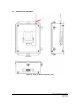
Figure 02: CAN-2 with external antenna (red) Figure 04: CAN-2 Bottom View 3.3 Figure 03: CAN-2 with internal antenna (red) Figure 05: CAN-2 Side View INSTALLATION 1. 2. 3. 4. 5. 6. 7. Determine the location of your antenna from Figures 01 through 03 (the antenna is designated with the red arrow). Be sure to mount the receiver antenna in direct line-of-sight of the operator and free from all obstructions.
3.4 REMOVAL OF CAN-2 FROM HOUSING It might be necessary to access the internal circuit board on the receiver to adjust the CAN terminating resistor jumper. To remove the CAN-2 receiver from the housing, first remove power from the CAN-2 receiver by turning off the master disconnect. Remove the connectors from the bottom of the receiver by squeezing in the release tabs on both sides of the connector.
3.5 CAN TERMINATING RESISTOR SETTING For CAN signaling to work correctly, the first and last devices on the CAN bus must have terminating resistors of 120 ohms. The CAN-2 has a built-in terminating resistor that can be enabled or disabled by a built-in jumper. After removing the CAN-2 receiver from the housing, locate the terminating resistor jumper (P2) on the PCB near the main connector in the lower right, as seen in Figure 07.
3.7 PIN OUT DIAGRAM AND DEFINITIONS Figure 09: Pin out diagram Table 1: Connector Connections PIN 1 2 3 4 5 6 7 8 9 10 11 12 FUNCTION CANL CANH CAN_REF CANL CANH -VBATT +VBATT USB D+ USB DUSB REF OUTPUT2 OUTPUT1 DESCRIPTION CANL CANH Common CANL CANH Common +12-24 VDC Power USB Data USB Data USB Common Output/ESTOP 2 Output/ESTOP 1 +VBATT (Pin 7) The CAN-2 is designed to work in any 12-24 VDC nominal (9-36 VDC max) powered equipment.
Figure 10: CAN-2 Machine Stop Wiring Additionally, make sure that a Machine Stop is provided elsewhere on the equipment in which the CAN-2 is installed in order to comply with all applicable Machinery Directives. CAN (Pins 1, 2, 4, and 5) There is only one CAN bus on the CAN-2. There are 2 sets of pins to support proper daisy chained connections to a CAN network. CAN Reference (Pin 3) On isolated CAN-2 devices pin 3 should be connected to the common pin of the device using the isolated CAN bus.
4.0 OPERATION During normal operation the CAN-2 receiver will receive commands from the transmitter and convert them to output or CAN signals. During these operations, the operator can verify that the receiver is online and functioning by interpreting the status LED lights on the front of the CAN-2 receiver. If there are errors during operation, the LED lights can help troubleshoot the problem. 4.
4.3.
5.0 PROGRAMMING WITH RCP Using the RCP software allows for simple configuration of the CAN-2, and allows for settings to be saved for future reference. WARNING THE USE OF RCP (RADIO CONTROL PROGRAMMER) IS INTENDED FOR USE BY AUTHORIZED PERSONS ONLY. CHANGES TO ANY RADIO DATA VALUE MAY LEAD TO UNEXPECTED, UNDESIRABLE, OR UNSAFE OPERATION OF EQUIPMENT AND FURTHERMORE MAY LEAD TO EQUIPMENT DAMAGE, PERSONAL INJURY, OR EVEN DEATH.
WARNING THE ACCESS CODES IN THE RECEIVER ARE UNIQUE AND FACTORY PRESET. DO NOT CHANGE THESE ACCESS CODES UNLESS YOU ARE REPLACING AN EXISTING RECEIVER AND ITS ACCESS CODE. CHANGING THIS CODE COULD MAKE IT COMMON WITH ANOTHER RECEIVER ACCESS CODE, WHICH COULD MOVE OTHER EQUIPMENT. NO TWO SYSTEMS IN ANY LOCATION SHOULD EVER HAVE THE SAME ACCESS CODES INDEPENDENT OF THE FREQUENCY. FAILURE TO FOLLOW THIS WARNING COULD RESULT IN SERIOUS INJURY OR DEATH, AND DAMAGE TO EQUIPMENT. 5.
WARNING CAN-2 RECEIVERS UTILIZING A DIFFERENT POWER SOURCE FROM THE COMPUTER SYSTEM BEING CONNECTED TO IT CAN HAVE A DIFFERENT GROUND POTENTIAL FROM THE COMPUTER SYSTEM. DIFFERENT GROUND POTENTIALS WILL DAMAGE EITHER THE COMPUTER SYSTEM OR THE CAN-2 RECEIVER. AN ISOLATED USB HUB MUST BE UTILIZED TO PREVENT DAMAGE TO THE CAN-2, THE COMPUTER SYSTEM BEING CONNECTED TO THE CAN-2, OR BOTH. 5.
For New Projects, Select Device Type After the New Projects icon is selected, a menu will open listing the available device types. Select the device type that matches the product you wish to program (selecting a project type will display a picture of the product for verification). Receive Device Data Checkbox At the bottom of the New Project window there is a check box that allows the system to automatically upload the setting values from the device upon connection.
WARNING IF THE “RECEIVE DEVICE DATA” CHECK BOX IS UNCHECKED, THE RCP PROGRAM WILL OVERWRITE ALL SETTING VALUES ON THE DEVICE WITH DEFAULT VALUES AND ANY SETTINGS CHANGED BY THE OPERATOR UPON SENDING THE PROGRAM TO THE DEVICE. ALL STORED VALUE SETTINGS WITHIN THE DEVICE WILL BE REPLACED, INCLUDING ANY PROJECT-SPECIFIC VALUES. MAGNETEK STRONGLY RECOMMENDS THAT THE “RECEIVE DEVICE DATA” CHECK BOX BE LEFT CHECKED.
programming of the device. The third tab is the FDP tab which is used to program new firmware into the device. For more information on the Programming and FDP tabs, please refer to the RCP User Guide. Unit Info Tab This page allows the user to view the receiver Project ID and serial number. The user can modify the receiver name, access code, RF channel, receiver timeout, and whether to use an internal or external RF antenna. CAN bus properties are able to be set in this page as well.
Unit Info Properties Frequency This field displays the operating frequency band of the receiver. The receiver Radio Frequency is set by the factory and cannot be modified by the user. Access Code The access code acts as the receiver address. The receiver will only listen to transmitters with the same access code. This feature is selectable by the user. NOTE: The transmitter must be set with the same access code as the receiver to properly communicate with each other.
RF Antenna This section allows the user to select between using the internal antenna that is built into the receiver or using the external antenna attachment (if available). NOTE: Selecting the external antenna when one isn’t available will result in reduced RF performance. Rx Timeout The Rx Timeout is the amount of time the unit will keep the machine stop outputs closed after the receiver has stopped receiving data from the transmitter.
5.4.2 Programming & Other RCP Software Functions NOTE: To program or read data from the CAN-2 the receiver must be turned on. Saving the Programming File Once programming is complete click the file tab at the top of the RCP screen to open the file menu. File location and name can be selected from this menu. Old files can be deleted, called up, modified and renamed by this same menu.
Reading the RCP Software Version 1. Select “Help.” 2. Select “About.” 3. RCP Software Version number will be displayed. Resetting CAN-2 Back to Factory Default Settings 1. Select the “Reset to Defaults” button. 2. A dialog box will pop up confirming that you want to proceed. Click the button “OK” to restore the factory default settings. On-screen prompts will confirm that the receiver has been reset to defaults or if there are any issues. 3.
6.0 CHANNEL AND FREQUENCY DESIGNATIONS 6.1 400 MHz Part 15 Table 3: 400MHz Channels Channel Designator 01 02 03 04 05 06 07 08 09 10 11 12 13 14 15 16 17 18 19 20 21 22 23 24 25 26 27 28 29 30 31 32 Frequency 433.000 MHz 433.050 MHz 433.100 MHz 433.150 MHz 433.200 MHz 433.250 MHz 433.300 MHz 433.350 MHz 433.400 MHz 433.450 MHz 433.500 MHz 433.550 MHz 433.600 MHz 433.650 MHz 433.700 MHz 433.750 MHz 433.800 MHz 433.850 MHz 433.900 MHz 433.950 MHz 434.000 MHz 434.050 MHz 434.100 MHz 434.150 MHz 434.
6.2 419 MHz Extended Channel Set Table 4: 419MHz Channels Channel Designator 1* 2* 3* 4* 5* 6* 7* 8* 9* 10* 11* 12* 13* 14 15 16 17 18 19 20 21 22 23 24 25 26 27 28 29 30 31 32 33 34 35 36 37 38 39 40 41 42 43 Frequency 418.950 418.975 419.000 419.025 419.050 419.075 419.100 419.125 419.150 419.175 419.200 419.250 419.275 416.000 416.050 416.100 416.150 416.200 416.250 416.300 416.350 416.400 416.450 416.500 416.550 416.600 416.650 416.700 416.750 416.800 416.850 416.900 416.950 417.000 417.050 417.
6.3 900 MHz Part 15 Table 5: 900MHz Channels Channel Designator 1 2 3 4 5 6 7 8 A B C D E F G H I J K L M N O P Q R S T U V W X 6.4 Frequency 903.30 MHz 906.30 MHz 907.80 MHz 909.30 MHz 912.30 MHz 915.30 MHz 919.80 MHz 921.30 MHz 902.30 MHz 904.10 MHz 904.30 MHz 905.10 MHz 905.50 MHz 905.70 MHz 906.60 MHz 908.70 MHz 908.90 MHz 909.10 MHz 910.10 MHz 910.70 MHz 911.00 MHz 911.20 MHz 912.00 MHz 914.20 MHz 914.40 MHz 914.60 MHz 914.80 MHz 915.80 MHz 917.40 MHz 923.20 MHz 927.00 MHz 927.30 MHz 2.
6.5 FCC Statements Compliance Statement (Part 15.19) This device complies with Part 15 of FCC rules. Operation is subject to the following two conditions: 1. This device may not cause harmful interference, and 2. This device must accept any interference received, including interference that may cause undesired operation. This portable transmitter with its antenna complies with FCC’s RF exposure limits for general population/uncontrolled exposure. Warning (Part 15.
7.0 TROUBLESHOOTING 7.1 TROUBLESHOOTING TABLE Problems Receiver will not turn on Possible Reasons Suggestions Supplied voltage is out of the Ensure the voltage is within 12-24VDC acceptable range nominal (9-36VDC max). Internal fuse has blown Incorrect system RF channel Contact the factory. Make sure the receiver and transmitter unit are both set to the same RF channel. Incorrect system access Make sure the receiver and transmitter both code have the same access code.
The CAN message being CAN messages are not being received by the receiver sent is not supported Outputs not functioning update. Verify that the setting of the terminating incorrect value resistor is correct for the application. Incorrect source address Ensure the correct baud rate is set by all devices on the bus. Make sure that the source address of the receiver is set correctly. The termination resistor is Ensure the termination resistor is set incorrectly appropriately set.
8.