MST/E Electric Shoe Brakes Mondel MST/E Electric Shoe Brakes Instruction Manual Part Number: 560022-R6 July 2006 © Copyright 2006 Magnetek Material Handling
Installation and Maintenance Instructions MST/E Electric Shoe Brakes SUPPLEMENTS FORMING PART OF THIS MANUAL: DATE OF MANUFACTURE: APPLICABLE DIMENSION PRINT: EXPLODED VIEW: PARTS LIST: 8/17/2006 Page 2 of 33 MST/E Electric Shoe Brakes Manual 560022-R6
Table of Contents Chapter 1.0: MST/E Electric Shoe Brakes Warnings and Cautions ................................................... 4 Chapter 2.0: General Description........................................................................................................ 7 Chapter 3.0: Application .................................................................................................................... 10 Chapter 4.0: Description of Operation.........................................................
Chapter 1.0: MST/E Electric Shoe Brakes Warnings and Cautions Read and Understand All Warnings And Cautions Printed In This Manual Before Commencing Installation, Adjustment Or Repair Chapter 5: INSTALLATION – Warnings and Cautions Anyone involved in the installation or service of this brake must have: • Received specific training. • Had experience on similar equipment. • Knowledge of the equipment on which the brake is installed. • The ability to understand the terminology.
Failure to properly center the brake and obtain uniform lining contact results in localized heating and, ultimately, reduced torque, which can cause injury or death. Chapter 6: ADJUSTMENT – Warnings and Cautions Protect against the possibility of movement due to the effects of gravity, wind or other source of energy, which has the potential to create a hazard when the brake is being worked on or is removed entirely.
Avoid contact with “live” terminals and prevent contaminant entry. Replace the terminal box cover as soon as connections are complete. Chapter 8: OPERATIONAL TEST – Warnings and Cautions Always perform an operational test of the brake after any replacement, adjustment, or repair. Read and understand the intent of the warnings published in this document – if in doubt, ask. In a hoist application, post observers to monitor the position of the hook if it travels out of sight of the operator.
Chapter 2.0: General Description 2.1: Mondel type MST/E spring applied, Hy-Thrust actuated general purpose brakes are designed for use on cranes and other severe braking applications in heavy industry. They can be used with any drive type applied to hoisting or horizontal travel motions. 2.2: There are two basic models of this versatile, high-speed, AC operated brake: Type MST with fixed value internal torque spring, and Type MST/E with an adjustable external torque spring. 2.
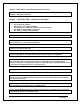
Figure 1 General Arrangement MST/E Electric Shoe Brake LINK ARM (ACTUATOR END) TORQUE ADJUSTMENT SCREW (B) PIVOT BLOCK BRAKE LEVER LINK ARM (OUTER END) DRIVE END PIVOT BRAKE ROD MANUAL RELEASE FILLER PLUG (NOTE 1) BRAKE SHOES OPTIONAL TIME DELAY VALVES EXTERNAL TORQUE SPRING HY-THRUST ACTUATOR FIXED END PIVOT TERMINAL WIRING BOX NOTE 1: FILL TO LOWER RIM OF FILLER HOLE. USE ONLY FLUID IDENTIFIED ON THE ACTUATOR NAMEPLATE.
Figure 1a General Arrangement MST/E Electric Shoe Brake With Automatic-Adjustment and Automatic-Equalization AUTOMATIC ADJUSTMENT (AA) BRAKE LEVER TORQUE ADJUSTMENT SCREW LINK ARM (ACTUATOR END) PIVOT BLOCK DRIVE END PIVOT MANUAL RELEASE LINK ARM (OUTER END) FILLER PLUG (NOTE 1) OPTIONAL TIME DELAYS BRAKE ROD TERMINAL WIRING BOX HY-TRUST ACTUATOR FIXED END PIVOT EXTERNAL TORQUE SPRING NOTE 1: FILL TO LOWER RIM OF FILLER HOLE. USE ONLY FLUID IDENTIFIED ON THE ACTUATOR NAMEPLATE. DO NOT OVERFILL.
Chapter 3.0: Application 3.1: The brake covered by this manual is type MST/E. This brake has an adjustable external torque spring and is generally applied on installations where the required torque cannot be predetermined within well defined limits. 3.2: For a given wheel diameter the Association of Iron and Steel Engineers (AISE) determines the prescribed torque, when applied to 30 and 60 minute rated motors in steel mill applications. 3.
Chapter 4.0: Description of Operation 4.1: The brake is spring applied and actuator released. A heavy-duty compression spring within the actuator pulls down on the brake lever and forces the shoes against the wheel. 4.2: The actuator piston rod extends when power is applied, the brake-shoe pressure removed and running shoe clearance established. 4.3: Subject to the effect of brake geometry, braking torque depends upon three major factors: 4.3.(a): The diameter of the wheel. 4.3.
4.12.(b): When the angle, through which the pin moves within the slot, does not allow contact with the sides of the slot, nothing happens! 4.12.(c): When the brake applies, after some minimal amount of lining wear, the pin will contact the side of the slot in the collar, which will advance the ratcheting mechanism and prepare for adjustment the next time the brake is released. 4.12.
Figure 2 MST/E Brake Shown With Typical Brake Release Lever Without Automatic Adjustment and Automatic Equalization BRAKE LEVER IN RELEASED POSITION ACTIVE STROKE BRAKE LEVER IN APPLIED POSITION TORQUE ADJUSTMENT SCREW (B) LO CK-NUTS (F) TOLERANCE +/- 1/ 32” ON ALIGNMENT BETWEEN BRAKE AND WHEEL HORIZONTAL CENTER LINES RESERVE STROKE TO LERANCE +/- 1/32” ON ALIGNMENT BETWEEN BRAKE AND WHEEL VERTICAL CENTER LINES TORQUE SPRING SETTING SCALE SHOE CLEARANCE EQUALIZING BOLT (Not available on MST/E with Au
Chapter 5.0: Installation 5.1: After unpacking, visually inspect the brake assembly to ensure that damage has not occurred during shipment and that there are no loose or missing parts. 5.2: Prepare the brake support structure and install the brake assembly subject to the following: 5.2.(a): Allow adequate clearance between the brake and adjacent obstructions to allow access for adjustment and maintenance. Brake shoe replacement requires space for complete withdrawal of the link arm pivot pins. 5.2.
5.7: Type MST/E brakes can also be wall mounted with the brake wheel shaft vertical. Again this requires the actuator hydraulic section filler plug to be at the highest point possible with the actuator horizontal. For this mounting arrangement both equalizing bolts may be required to ensure equal shoe clearance. 5.8: For any other mounting arrangements consult factory. 5.
Chapter 6.0: Adjustment 6.1: Following any adjustment or repair of the brake, test operation of the brake as described under “Operational test”, Chapter 8. 6.2: Complete adjustment is required following any rework where any settings were disturbed. Table 1 BRAKE WHEEL SIZES (Inches) 6 8 10 13 16 19 TYPICAL RUNNING CLEARANCE BETWEEN LINING AND BRAKE WHEEL (Inches) MAXIMUM FULL SPEED BRAKE WHEEL run-out (Inches) 0.014 0.016 0.020 0.026 0.032 0.038 0.006 0.008 0.010 0.013 0.016 0.019 Notes: 1.
6.4: Actuator Stroke Adjustment 6.4.(a): When power is applied to the actuator the piston will be caused to extend. This will compress the external spring and raise the brake lever to provide operating clearance between the shoes and the wheel. 6.4.(b): When power is removed from the actuator, the spring will retract the lever until the shoe pressure on the wheel prevents any further lever movement as the reserve stroke setting is attained and the intended brake torque achieved. 6.4.
6.5.(a).(iii): The correct linings are fitted. 6.5.(a).(iv): The linings are in good condition and bedding is completed. 6.5.(a).(v): The brake wheel is aligned and in good condition. 6.5.(b): Torque adjustment for Mondel MST/E brakes is adjustable on site. Tighten or loosen screw (B), see Fig. 2, to set the torque within the prescribed range shown on the scale. The torque setting is obtained by matching the top of the spring-block to a line on the spring scale. 6.6: Automatic Equalization Assembly 6.6.
(AE) ARM SIDE CASTLE NUT SIDE 6.6.(g).(i): Install a castle nut, tighten nut until the flat washer is FLUSH with the side of the Automatic Equalization arm. Loosen or tighten the nut no more than 1/8 of a turn, only enough to align the nearest cotter pin slot and hole. Install the cotter pin. This completes the assembly. 6.7: Shoe Clearance Adjustment 6.7.(a): The total available shoe clearance is determined by the active stroke of the actuator and the brake lever ratio.
6.8: Parallel Shoe Gap Adjustment 6.8.(a): For optimum lining wear distribution, brake shoes have controlled freedom to align with the wheel contour as the linings wear. 6.8.(b): Each brake shoe holder pivots on its link arm. Its freedom to rotate under gravity is controlled by a shoe holder friction mechanism. 6.8.(c): Spring loaded pins in each link arm bear against the inside of the shoe (Fig. 3). This provides tension to maintain shoe alignment when the brake is released. The tension is not adjustable.
Figure 3 Section Through Shoe And Link Arm Drawn To Reveal Tension Device BRAKE ROD WMF FILE WIP 010212 BRAKE WHEEL BRAKE SHOE SHOE ALIGNMENT TENSION DEVICE Figure 3 SECTION THROUGH SHOE AND LINK ARM DRAWN TO REVEAL TENSION DEVICE 8/17/2006 Page 21 of 33 MST/E Electric Shoe Brakes Manual 560022-R6
Figure 3A Type AE Automatic Equalization Mechanism Assembly (AE) IDLER PIVOT PIN FRICTION BOLT AUTO EQUALIZE ARM COTTER PIN COTTER PIN AUTO EQUALIZE ARM BELLVILLE WASHER (3) COTTER PIN FLAT WASHER CASTLE NUT 8/17/2006 Page 22 of 33 MST/E Electric Shoe Brakes Manual 560022-R6
Chapter 7.0: Electrical Detail 7.1: Operation of the actuator is not dependant of the direction of motor rotation. The cable leads can be connected to the U1, V1 and W1, (T1, T2, T3), terminals in any phase sequence. Figure 4 Electrical Connections 7.2: The motor leaves the factory already arranged for the specified voltage, which is also shown on the nameplate. 7.
Chapter 8.0: Operational Test 8.1: Heed all warnings and cautions in addition to the owners’ safety procedures. 8.2: Follow all standards and local statutes. 8.3: Remove any drum chocks on a hoist application. 8.4: As a preliminary test of the brake without load, energize the actuator for one short jog. If the brake fails to stop and hold the motion stationary, repair or re-adjust the brake as necessary. Visually inspect the brake during operation to ensure all adjustments are correct.
8.13.(a).(ii): Linings thinner than the original equipment may result in contact with the wheel only across the middle and cause vibration during stops. 8.13.(b): Do no use re-lined shoes where the castings are damaged, worn or distorted. 8.13.(c): Square the brake to the wheel for optimum contact between the linings and the wheel. 8.13.(d): Type MST/E brakes utilize shoe clearance equalizing bolts to equalize brake shoe clearance; ensure that they are correctly adjusted in accordance with Chapter 6. 8.13.
Chapter 9.0: Maintenance and Repair NEMA Standard ICS 9-1993, Part 1 recommends that brakes be fitted with new or re-lined shoes before the lining material is worn excessively. Refer to Table 4 for minimum thickness. 9.1: Replacing the Brake Shoes 9.1.(a): Remove and reinstall the brake shoes as follows. Use a lifting devise as necessary. 9.1.(a).(i): On a hoist lower the load to the floor and disconnect the load from the bottom block. 9.1.(a).
Figure 5 Brake Shoe Removal (2) (4) (1) (3) (8) (6) (7) (5) 9.1.(a).(xii): Before starting shoe installation, check that the brake surface of the wheel is clean and free from oil and grease. 9.1.(a).(xiii): Next, verify that the lining surface will be true to the wheel when the shoe is installed. Carefully check lining contact with the wheel. Remove any high spots with emery paper to ensure 60% contact between the lining and the wheel. 9.1.
9.1.(h): Refer to Chapter 6 and adjust the brake shoe clearance as required. 9.1.(i): Refer to Chapter 8; bed and test the brake as described. 9.2: Removing The Actuator 9.2.(a): Secure against any possibility of an unexpected movement when the actuator is removed. 9.2.(b): Lower the load to the floor and disconnect the load from the bottom block. 9.2.(c): Reset the bottom block on the floor, or on a suitable support. Chock the drum to prevent rotation. 9.2.
9.2.(f): Secure or support the actuator before attempting to remove the pivot pins. 9.2.(g): Refer to Fig. 6: remove the cotter pins and withdraw the pivot pins attaching the actuator to the brake body. 9.2.(h): Remove the complete actuator using appropriate lifting devices. 9.2.(i): Should service be required, return the actuator to Magnetek for repairs. 9.3: Re-Installing The Actuator 9.3.(a): Verify adequate means are still in place to protect unexpected movement when the actuator is replaced. 9.3.
9.5.(g): Re-install the shoe assemblies as described under the topic “Replacing the Brake Shoes”. 9.5.(h): Re-attach the brake rod to the brake lever. 9.5.(i): Ensure that all shoe holder pivot and hitch pins are correctly installed. 9.5.(j): Test the operation of the brake as described under the topic “Operational Test”. 9.5.(k): Install the brake wheel as described elsewhere. 9.5.(l): Verify the brake is still properly centered over the wheel. Make any adjustments as required.
9.8.(d): If additional fluid is necessary for any reason, use only the fluid identified on the nameplate to ensure compatibility with the installed seals and the specified operating temperature range. DO NOT OVER-FILL. 9.8.(e): Table 3 specifies Recommended Hydraulic Fluid types for a range of ambient temperatures.
Chapter 10.0: Replacement Parts 10.1: Brake Lining Replacement 10.1.(a): As a general guide, Magnetek recommends that brake linings be replaced when the linings wear down to 1/16” minimum thickness. Table 4, taken from standard ICS 9-1993, Part 1: Electromagnetic Brakes, shows NEMA’s recommended range of minimum lining thickness for bonded and riveted linings on brake wheels from 8” to 19” diameter… Table 4 Wheel Diameter (Inches) Maximum RPM Ductile Iron Minimum Wheel Dia.
Chapter 11.0: Long Term Storage 11.1: If a brake assembly will not be installed immediately, it can be stored indoors in a dry location indefinitely or outdoors for a reasonable time if adequately protected from moisture and corrosive atmosphere. The brake assembly must always be protected from direct exposure to the elements unless specifically treated at the factory for use in that environment.