
User Guide


Chapter 6.0: Adjustment
6.1: Following any adjustment or repair of the brake, test operation of the brake as described under
“Operational test”, Chapter 8.
6.2: Complete adjustment is required following any rework where any settings were disturbed.
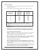
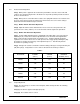
Table 1
BRAKE WHEEL
SIZES (Inches)
TYPICAL RUNNING
CLEARANCE
BETWEEN LINING
AND BRAKE
WHEEL (Inches)
MAXIMUM FULL
SPEED BRAKE
WHEEL run-out
(Inches)
6
8
10
13
16
19
0.014
0.016
0.020
0.026
0.032
0.038
0.006
0.008
0.010
0.013
0.016
0.019
Notes:
1. Refer to “Brake Installation” and “Replacing the Brake Shoes” for adjustment
instructions.
2. Evaluate brake wheel run-out at full speed. It must not exceed value shown in this
table.
6.3: Manual Operation
6.3.(a): Brake installation, shoe replacement, and actuator replacement, described elsewhere,
require the brake to be released and reapplied without energizing the actuator. When type “S”
Latching Hand Release is fitted, it can be used; or it can be manually over-ridden as follows:
6.3.(b): Brakes without Automatic Adjustment:
6.3.(b).(i): To manually release the brake: Adjust the brake rod hex-nuts – to increase the brake
rod length – reducing the “reserve stroke” until the piston rod is no longer visible. Continue
adjustment until there is sufficient lining to brake wheel clearance.
6.3.(c): To manually apply the brake: Adjust the brake rod hex-nuts – to decrease the brake rod
length – increasing the “reserve stroke” until the linings contact the brake wheel. Continue until
the brake release lever begins to rise. Proceed to “Actuator Stroke Adjustment”.
6.3.(d): Brakes with Automatic Adjustment:
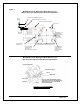
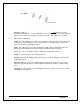
6.3.(e): To manually release the brake: Refer to Fig. 2A, withdraw drive pin (E), then carefully
rotate the mechanism by hand to increase the brake rod length and, at the same time, reduce the
reserve stroke until the piston rod is no longer visible. Continue adjustment until there is sufficient
shoe/wheel clearance.
8/17/2006 Page 16 of 33 MST/E Electric Shoe Brakes Manual
560022-R6
6.3.(f): To manually apply the brake: Refer to Fig. 2A and withdraw drive pin (E), then rotate the
mechanism by hand to decrease the effective brake rod length until the linings contact the wheel
and the brake lever begins to rise. Proceed to “Actuator Stroke Adjustment”.