Quattro™ DC Elevator Drive Technical Manual TM7310 rev 01 © 2006 Magnetek Elevator
WARRANTY Standard products manufactured by the Company are warranted to be free from defects in workmanship and material for a period of one year from the date of shipment, and any products which are defective in workmanship or material will be repaired or replaced, at the Company’s option, at no charge to the Buyer. Final determination as to whether a product is actually defective rests with the Company.
Table of Contents Introduction ............................................................................................................. 10 Drive Ratings and Specifications ....................................................................................................... 10 Software Operating Features............................................................................................................. 10 Drive Model Numbers ....................................................................
LS Power Data D3 submenu ............................................................................................................. 69 Utility U0 menu ........................................................................................................ 70 Fault F0 menu.......................................................................................................... 76 Maintenance ............................................................................................................
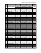
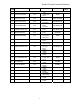
Quattro DC Quick Parameter Reference Sub Parameter Units Range menu A1 Drive A1 Submenu – See Drive A1 submenu on page 30.
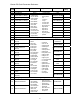
Quattro DC Quick Parameter Reference Sub Parameter Units Range Default menu A2 S-Curves A2 Submenu – See S-Curves A2 submenu on page 39.
Quattro DC Quick Parameter Reference Sub Parameter Units Range Default menu A3 Multistep Ref A3 Submenu – See Multistep Ref A3 submenu on page 41.
Quattro DC Quick Parameter Reference Site Sub Parameter Units Range Default Setting menu A5 Line Side Power converter A5 Submenu – See Line Side Power Converter on page 46.
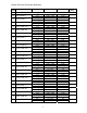
Quattro DC Quick Parameter Reference Sub Parameter Units Range menu User Switches C1 Submenu continued … C1 C1 PreTorque SOURCE none C1 PreTorque LATCH none C1 PTorq LATCH CLCK none C1 FAULT RESET SRC none C1 OVERSPD TEST SRC none C1 BRAKE PICK SRC none C1 BRAKE PICK CNFM none C1 BRAKE HOLD SRC none C1 RAMPED STOP SEL none C1 RAMP DOWN EN SRC none C1 BRK PICK FLT ENA none C1 BRK HOLD FLT ENA none C1 EXT TORQ CMD SRC none C1 DIR CONFIRM none C1 S-CURVE ABORT none
Quattro DC Quick Parameter Reference Sub Parameter Units Range Default menu Logic Inputs C2 Submenu – See Logic Inputs C2 submenu on page 61. C2 C2 N.C.
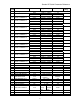
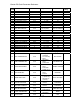
Quattro DC Quick Parameter Reference Menu Parameter Unit U1 Password U1 Submenu Menu Parameter Unit D1 Elevator Data Submenu D1 D1 D1 D1 D1 D1 D1 D1 D1 D1 D1 D1 D1 D2 D2 D2 D2 D2 D2 D2 D2 D2 D2 D2 D2 D2 D2 D2 D2 D2 D2 D2 D2 D3 D3 D3 D3 D3 D3 D3 D3 D3 D3 D3 D3 D3 D3 Speed Command Speed Reference Speed Feedback Speed Error Pre-Torque Ref Ext-Torque Cmd Spd Reg Torq Cmd Tach Rate Cmd Aux Torque Cmd Est Inertia Rx Com Status Logic Outputs Logic Inputs ft/min or m/sec ft/min or m/sec ft/min or m/sec ft/min
Quattro DC Introduction • User choice of P-I type or MagneTek exclusive E-Reg, elevator velocity regulators (see pages 59 and 60) • Optional CEMF speed regulator for use during initial construction stage start-up • Torque Feed-Forward when available from the car controller (see pg 23) • Pre-Torque at drive start to reduce roll-back (see pg 23) • Controlled torque Ramp-Down to prevent elevator brake thumping at stops (see pg 23) • Internal frequency notch filter to reject rope resonance interference (see pg
Quattro DC Introduction The next option consists of shipping, either domestically or internationally. Due to international standards, the shipping crate must be heat-treated. The final option section determines the type of motor contactor and Magnetek Operator. The Magnetek Operator is not required to start running, but allows for easy access to parameters, overspeed test, and auto tuning.
Quattro DC Startup Guide 3. Never allow wire leads to contact metal surfaces. Short circuit may result. 4. SIZE OF WIRE MUST BE SUITABLE FOR CLASS I CIRCUITS. 5. Motor lead length should not exceed 20m (60 ft). If lead length must exceed this distance, contact Magnetek for proper installation procedures. 6. The following are required to be contained in individual conduit runs: 3-phase incoming power, control power, DC armature wires, and DC shunt field. 7.
Quattro DC Startup Guide − problems, the following electrical and mechanical considerations are suggested. Open F1 and F2 and ensure control power brought into fuse F1 and F2 is 230VAC! IMPORTANT: Double-check all the power wires and motor wires to make sure that they are securely tightened down to their respective lugs (loose wire connections may cause problems at any time). IMPORTANT Proper encoder speed feedback is essential for a drive to provide proper motor control.
Quattro DC Startup Guide 2. CONTRACT MTR SPD (A1) parameter programs the motor speed at elevator contract speed in RPM. Low speed inspection mode Run the drive in low speed inspection mode and… 1. Verify encoder polarity, the motor rotation should match the encoder phasing. The equivalent of swapping A and /A can be done with the ENCODER CONNECT (C1) parameter. Line voltage setup Enter / Verify the line voltage parameter: 1.
Quattro DC Interconnections Interconnections QUATTRO SIGNAL CONNECTIONS – A6 TB1 A9JCC1-4 Contact A9JCC1-2 Cfirm 6* 5* A9JCC1-1 +24 VISO 1 LI1 +24VISO 47 LI2 +24VISO 48 2 CTR PWR Sense *Located on A9TB1 To/ From Encoder, Use +5 or +12 Volt supply power From Customer Analog Outputs TB1 11 Logic Inputs LO1 25 Open Collector Outputs, 24 VDC, 15mA Max 3 LI3 4 LI4 5 LI5 LO4 28 LO2 26 LO3 27 6 LI6 LO5 29 7 LI7 LO6 30 8 LI8 LO7 31 9 LI9 LOC 32 10 LIB C_24VISO 33 43 C_
Quattro DC Interconnections L(1) L(2) L(3) GND Control Power * Note 1 230VAC hi * Note 1 230VAC lo To Quattro Drive F1 F2 * Note 1 TB1K1 K1 TB1 ME TB1 Internal Control Power H(X) H(1) Provided for the Primary side of the 230V control power transformer Safety Chain A24 4 3 Located on A9 TB1 SWout (+) 2 Motor Field Control DCout (-) 3 (F1) * Note 1 ME ME ME (21) (22) (13) (14) (43) (44) Motor Contactor Auxiliaries ME (4) (3) K1 DBR 1-4 Part of A9 ME ME DBR (A1) * Note 1 5-8 Hoist
Quattro DC Interconnections Logic Inputs The Quattro DC’s nine programmable logic inputs are opto-isolated. For more information on programming logic inputs, see Logic Inputs C2 submenu on page 61. The inputs become “true” by closing contacts or switches between the logic input terminal and voltage source common (or voltage source). The inputs are sourcing inputs – nominally sitting at common and when the contacts or switches are closed, turning “true” at 24VDC.
Quattro DC Interconnections For more on the multiplier gain or bias parameters, see Drive A1 submenu on page 30. The scaling of the analog input signals, with BIAS set to 0.00 and MULT set to 1.
Quattro DC Interconnections Relay Outputs The Quattro DC’s two programmable relay logic outputs are Form-C relays. The have both normally open and normally closed contacts. The specifications for each relay are as follows: Relay 1 • 2A at 30VDC or 1A at 230VAC Relay 2 • 2A at 30VDC or 1A at 230VAC Logic Outputs The Quattro DC’s seven programmable logic outputs are opto-isolated, open collector. The outputs are normally open and can withstand an applied maximum voltage of 30VDC.
Quattro DC Interconnections For more on the gain or offset parameters, see section Drive A1 submenu on page 30. Analog Outputs The Quattro DC has two programmable differential analog output channels. The two analog output channels were designed for diagnostic help. For more information on programming the analog output channels, see Analog Outputs C4 submenu on page 65. The analog output channels are bipolar and have a voltage range of ±10VDC and current draw of +/- 4mA.
Quattro DC Drive Sequencing Pre-charge Drive Sequencing Field Enable (input) Stand-by On Boost On Pre-charge Cnfrm Boost On Confirm NORMAL operating sequence 1. Motor field current is at Stand-By during drive idle. The No Faults relay is active. Full-Field and Run command signals are OFF. Motor contactor Safety circuits may be open or closed. The DC bus will remain charged with regulated voltage as long as the drive is providing motor field current. 2.
Quattro DC Drive Sequencing ABNORMAL Operation Sequence 1. If a Drive or Drive Sequence Fault occurs the Drive will immediately open the motor contactor, de-energize the Brake Pick, Brake Hold, and Drive OK Relays if so programmed. May be caused by: a. “Fatal Error” drive Faults including loss of serial communications b. Opening of the contactor power Safety circuit while the contactor is pulled in c. Loss of correct motor contactor or Brake Relay feedback. 2.
Quattro DC Drive Operation and Feature Overview requires SPD COMMAND SRC (C1) to be set to SERIAL. Drive Operation and Feature Overview Pre-Torque The Quattro DC drive is a velocity and torque regulated motor drive designed specifically for operating elevators. Many of the features described below can be selectively programmed to customize an individual application. When enabled, the speed error integrator will be pre-conditioned by the supplied pre-torque signal before starting the regulator.
Quattro DC Drive Operation and Feature Overview there will be no timed delay for current rampdown. This time may be adjusted by the function RAMPED STOP TIME (A1). Over-Speed Test A reference speed multiplier is provided to help testing of the elevator governor over-speed trip. This feature will automatically return to normal at the completion of each elevator run.
Quattro DC Drive Operation and Feature Overview Status Indicator Lights MONITOR / Adjust / Set-up Parameters: Five status indicator lamps are provided on the front panel of the drive. The values of all adjustments and set up parameters are stored locally in non-volatile drive memory. Monitoring of live data status and modification of parameter values can be accomplished by sequences over the serial link or the Magnetek Operator.
Quattro DC Parameters Parameters Parameter Introduction This section describes the parameter menu structure of the Magnetek Operator, how to navigate this menu structure, and a detailed description of each parameter. DISPLAY 1 D0 D1 ELEVATOR DATA RUN/FAULT SUB MENU DATA ENT Parameters are grouped under six major menus: • • • • • • Menus ADJUST A0 CONFIGURE C0 UTILITY U0 FAULTS F0 DISPLAY 1 D0 DISPLAY 2 D0 Each menu has a number of sub-menus.
Quattro DC Parameters Navigation at the Sub-menu Level When in the sub-menu level, the SUB-MENU LED on the digital operator is lit. At the submenu level, the positioning keys work slightly different than they did at the menu level. The up and down arrow keys now select separate items in the sub-menu. Menu Navigation The digital operator keys operate on three levels, the menu level, the sub-menu level and the entry level. At the menu level, they function to navigate between menus or submenus.
Quattro DC Parameters Parameter Tree Display D0 → Elevator Data D1 • • • • • • • • • • • • • Adjust A0 → Drive A1 • • • • • • • • • • • • • • • • Speed Command Speed Reference Speed Feedback Speed Error Pre-Torque Ref Ext-Torque Cmd Spd Reg Torq Cmd Tach Rate Cmd Aux Torque Cmd Est Inertia Rx Com Status Logic Outputs Logic Intputs → MS Power Data Contract Car Spd Contract Mtr Spd Response Inertia Inner Loop Xover Current Limit Gain Reduce Mult Gain Chng Level Tach Filter BW Tach Rate Gain Spd Phase Mar
Quattro DC Parameters Configure C0 → User Switches C1 • • • • • • • • • • • • • • • Spd Command Src Run Command Src Field Ena Src Hi/Lo Gain Src Speed Reg Type Motor Rotation Encoder Connect Spd Ref Release Cont Confirm Src Tach Filter Enable PreTorque Source PreTorque Latch Ptorq Latch Clck Fault Reset Src Overspd Test Src → Logic Inputs C2 • • • • • N.C.
Quattro DC Drive Parameters A1 Adjust A0 menu Drive A1 submenu Parameter Description CONTRACT CAR SPD (Contract Car Speed) Adjusts the elevator contract speed in feet per minute (fpm) or meters per second (m/s). CONTRACT MTR SPD RESPONSE INERTIA INNER LOOP XOVER CURRENT LIMIT GAIN REDUCE MULT GAIN CHNG LEVEL Units Default Range fpm 400.0 0.0 – 1500.0 m/s 2.000 0.00 – 8.00 1130.0 (Contract Motor Speed) Sets motor rpm when commanded to run at elevator contract speed.
Quattro DC Drive Parameters A1 Parameter Description Units (Tach Filter Bandwidth) Breakpoint of rad/sec tachometer / encoder feedback signal. (Tach Rate Gain) Used to help reduce the TACH RATE effects of rope resonance. It should be none GAIN adjusted only after the INERTIA and RESPONSE have been set correctly. (Speed Phase Margin) This parameter sets the phase margin of the speed regulator assuming a pure inertial load.
Quattro DC Drive Parameters A1 Parameter Description (Over speed Level) Sets the percentage of rated speed the drive uses (in OVERSPEED conjunction with OVERSPEED TIME, LEVEL below) to determine when an OVERSPEED fault occurs. Units in percent of contract speed (Over speed Time) Sets the time that the OVERSPEED drive can be at or above the OVERSPEED TIME LEVEL (A1), before the drive declares an OVERSPEED FLT.
Quattro DC Drive Parameters A1 Parameter EXT TORQUE BIAS Description (External Torque Bias) This parameter subtracts an effective voltage to the actual analog pre torque / torque command (channel 2) voltage signal. Note: Drive automatically limits current at 300% or the value in CURRENT LIMIT (A1). For more information, see Analog Inputs on page 18 and Pre-Torque / Torque Feed Forward on page 23.
Quattro DC Drive Parameters A1 Parameter ANA OUT 1 GAIN ANA OUT 2 GAIN Description Default Range none 1.0 0.0 – 10.0 Y N none 1.0 0.0 – 10.0 Y N sec 5 0 – 120 Y N faults 3 0 – 10 Y N % 80.00 0.00 –110.00 Y N sec 0.00 0.00 – 0.99 Y Y % 0.00 0.00 – 2.00 Y Y sec 0.00 0.00 – 9.99 Y Y sec 0.00 0.00 – 5.00 Y Y (Digital to Analog #1 Output Gain) Adjusts the scaling for the Analog Output Channel #1. NOTE: value of 1.0 = 0 to 10VDC signal.
Quattro DC Drive Parameters A1 Parameter Description (Torque Limit Message Delay) This parameter determines the amount of time TRQ LIM MSG the drive is in torque limit before the “HIT DLY TORQUE LIMIT” alarm message is displayed. (Rollback Gain) This parameter increases the sensitivity (or gain) of the speed regulator during the start in the interval ROLLBACK between “Speed Regulator Release” and GAIN “Reference Release”. The parameter acts as a multiplier to the existing speed regulator gain.
Quattro DC Drive Parameters A1 Detailed descriptions HPV 900 Parameter Settings HI/LO GAIN SRC = internal GAIN REDUCE MULT = 80% GAIN CHNG LEVEL = 10 % RESPONSE = 10.0 rad/sec GAIN CHNG LEVEL (Gain Change Level ) Works in conjunction with HI/LO GAIN SRC in menu C0. When the gain control source is set to internal, this parameter sets the speed reference level that controls the Hi/Lo gain switch.
Quattro DC Drive Parameters A1 RUN DELAY TIMER This parameter allows the user to delay the drive’s recognition of the RUN signal SPD DEV LO LEVEL and SPD DEV HI LEVEL (Speed Deviation Low / High Level) These two functions are available to indicate how the speed feedback is tracking the speed reference. • Speed Deviation Low – indicates that the speed feedback is tracking the speed reference within a defined range.
Quattro DC Drive Parameters A1 NOTCH FILTER FRQ (Notch Filter Center Frequency) Although originally created for gearless applications where elevator rope resonance is sometimes an issue, this filter affects the torque command output of the speed regulator and will filter out specific frequencies. By filtering a specific frequency, the speed regulator will avoid exciting a mechanical resonance if one exists at that frequency.
Quattro DC Drive S-Curves A2 There are four S-curve patterns available in the drive and each S-curve is customized by six parameters: Parameters for S-curve-0 (SC0): • ACCEL RATE 0, DECEL RATE 0, ACCEL JERK IN 0, ACCEL JERK OUT 0, DECEL JERK IN 0, and DECEL JERK OUT 0 Parameters for S-curve-1 (SC1): • ACCEL RATE 1, DECEL RATE 1, ACCEL JERK IN 1, ACCEL JERK OUT 1, DECEL JERK IN 1, and DECEL JERK OUT 1 Parameters for S-curve-2 (SC2): • ACCEL RATE 2, DECEL RATE 2, ACCEL JERK IN 2, ACCEL JERK OUT 2, DECEL JERK
Quattro DC Drive S-Curves A2 Parameter Description ACCEL RATE 0 Acceleration rate limit DECEL RATE 0 Deceleration rate limit ACCEL JERK IN 0 Rate of increase of acceleration, up to ACCEL RATE, when increasing elevator speed ACCEL Rate of decrease of acceleration to zero when JERK OUT 0 approaching contract elevator speed DECEL JERK IN 0 Rate of increase of deceleration, up to DECEL RATE, when decreasing elevator speed DECEL Rate of decrease of deceleration to zero when JERK OUT 0 slowing the elev
Quattro DC Multistep Ref A3 Submenu Multistep Ref A3 submenu The multi-step speed reference function is one possible way for the drive to accept speed command. To use this function, the user can enter up to fifteen speed commands (CMD1 – CMD15) and assign four logic inputs as speed command selections. An example of the use of the multi-step command is as follows: • All speed commands are positive. • CMD0 specifies zero speed. • CMD1 specifies leveling speed. • CMD2 specifies inspection speed.
Quattro DC Multistep Ref A3 Submenu Parameter Description Units Default Range SPEED COMMAND 1 Multi-step speed command #1 ft/min 0.0 -3000.0 – +3000.0 m/sec 0.000 -16.000 – +16.000 SPEED COMMAND 2 Multi-step speed command #2 ft/min 0.0 -3000.0 – +3000.0 m/sec 0.000 -16.000 – +16.000 SPEED COMMAND 3 Multi-step speed command #3 ft/min 0.0 -3000.0 – +3000.0 m/sec 0.000 -16.000 – +16.000 SPEED COMMAND 4 Multi-step speed command #4 ft/min 0.0 -3000.0 – +3000.0 m/sec 0.
Quattro DC Motor Side Power Convert A4 Submenu Motor Side Power Convert A4 submenu Parameter ARM RESISTANCE ARM INDUCTANCE MTR REV VLT LIM IF REG INT GAIN IF REG PROP GAIN AUTO TUNE MOTOR GAIN SELECTION Description (Armature Circuit Resistance) Affects tuning of the armature current regulator. Load this parameter with known or measured value. Only used is GAIN SELECTION (A4) is set to Manual. (Armature Circuit Inductance) Affects tuning of the armature current regulator.
Quattro DC Motor Side Power Convert A4 Submenu Parameter GAIN BANDWIDTH A GAIN BANDWIDTH F PWM FREQ FAN OFF DELAY Description Units (Gain Bandwidth Armature) If GAIN SELECTION (C1) is set to MANUAL, this parameter is used to convert ARM RESISTANCE (A4) and ARM INDUCTANCE (A4) into the integral and proportional gains used by the current regulator.
Quattro DC Motor Side Power Convert A4 Submenu Parameter Description Units (Main Fan Control Select) Selects primary method of cooling fan control. − AUTO – All cooling fans turn OFF after Fan Off Delay time, after DSPR becomes active. − TEMP – Fan speed is responsive to highest measured temperature of IGBT MAIN FAN CONTROL modules.
Quattro DC Line Side Power Convert A5 Submenu Line Side Power Converter A5 submenu NOTE: The only parameter that should ever need to be adjusted is INPUT L-L VOLTS. Other parameters are for Magnetek Engineering use only.
Quattro DC Motor A6 Submenu Motor Parameters A6 submenu Parameter Description (Motor Identification) This parameter allows for the selection of specific sets of MOTOR ID motor parameters. This is yet to be determined for DC machines. (Rated Armature Amps) Motor armature RATED MOTOR amps. Note: value should be obtained CURR from the motor nameplate. (Rated Armature Voltage) Rated motor armature circuit voltage. Note: value ARMATURE VOLTS should be obtained from the motor nameplate.
Quattro DC Motor A6 Submenu Parameter Description (Motor Overload Start Level) This parameter defines maximum current at which motor can run continuously OVLD START LEVEL without triggering the motor overload. One of the two parameters that define the motor overload curve. Set as a percent of Rated Motor Current.
Quattro DC Motor A6 Submenu 10,000 1000 default motor overload trip time (seconds) Curve #1 curve #3 OLVD TIME OUT = 70 sec 100 Curve #2 Curve #3 curve #1 OLVD TIME OUT = 60 sec curve #2 OLVD TIME OUT = 40 sec 10 110% 130 % 150% 170% 190% 210% current (percentage of rated motor current) curve #1 OLVD START LEVEL = 110% curve #2 OLVD START LEVEL = 110% curve #3 OLVD START LEVEL = 120% Figure 14: Motor Overload Curve .
Quattro DC User Switches C1 Configure C0 menu User Switches C1 submenu Parameter SPD COMMAND SRC RUN COMMAND SRC FIELD ENA SOURCE Description Default Choices (Speed Command Source) This parameter designates the source of the drive’s speed command. The four possible sources for the speed command are following: • Serial Channel - a RS-422 serial port located on the customer interface PCB. • Analog Channel – a bipolar (±10V) signal.
Quattro DC User Switches C1 Parameter HI/LO GAIN SRC Description Default (High / low gain change switch source) This parameter determines the source of the high / low gain switch. The speed regulator high / low gain function was developed in response to high performance elevator requirements where the resonant nature of the elevator system interferes with the speed response of the drive. For more information, see HI/LO GAIN SRC on page 59.
Quattro DC User Switches C1 Parameter MOTOR ROTATION ENCODER CONNECT SPD REF RELEASE CONT CONFIRM SRC TACH FILTER PreTorque SOURCE Description Default Choices (Motor Rotation) This parameter allows the user to change the direction of the motor rotation. As an example, if − forward the car controller is commanding the up FORWARD direction and the car is actually going in a down − reverse direction, this parameter can be changed to allow the motor rotation to match the car controller command.
Quattro DC User Switches C1 Parameter PreTorque LATCH Ptorq LATCH CLCK FAULT RESET SRC Description Default Choices (PreTorque Latch) If Pre-Torque latching is NOT selected, the Pre-Torque signal must be valid when the speed regulator is commanded to run. For verification on timing, see NORMAL operating sequence on page 21. Some car controllers send both analog pretorque and speed commands . To facilitate this, the Drive has the option of latching the pretorque command.
Quattro DC User Switches C1 Parameter Description Default (Overspeed Test Source) This switch determines the source of the overspeed test. Operation of the overspeed test OVERSPD function is specified by the OVRSPEED MULT TEST SRC (A1) parameter. Regardless of the setting of this parameter, the user can call for the overspeed test via the Digital Operator.
Quattro DC User Switches C1 Parameter Description Run Hidden lock Item out Default Choices NONE − none − serial − analog input Y Y − disabled − enabled Y Y (Torque Command Source) Sets the source of an external torque command, if any.
Quattro DC User Switches C1 Parameter S-CURVE ABORT ENCODER FAULT PRIORITY MESSAGE Description Default (S-Curve Abort) This parameter, S-CURVE ABORT (C1), addresses how the S-Curve Speed Reference Generator handles a reduction in the speed command before the S-Curve Generator has reached its target speed. Disabled: With a normal S-curve function, a change in the speed command is never allowed to violate the defined acceleration or jerk rates.
Quattro DC User Switches C1 Parameter Description Default STOPPING MODE (Multi-step Stopping Mode Selection) When the speed command source is set to multi-step (SPD COMMAND SRC (C1)=multistep), the parameter, STOPPING MODE (C1), determines the stopping mode of the Drive. The two selectable methods for the Stopping Mode parameter are “Immediate” and “Ramp to stop”.
Quattro DC User Switches C1 Parameter Description Default (Auto Stop Function Enable) When the speed command source is set to multi-step or serial (SPD COMMAND SRC (C1)=multi-step or serial), the parameter determines the stopping mode of the drive. The two selectable methods for the STOPPING MODE (C1)* parameter are “Immediate” and “Ramp to stop”. The Auto Stop function determines how the drive logic will respond to a zero or non-zero speed command.
Quattro DC User Switches C1 Detailed descriptions HPV 900 Parameter Settings HI/LO GAIN SRC = internal GAIN REDUCE MULT = 80% GAIN CHNG LEVEL = 10 % RESPONSE = 10.0 rad/sec HI/LO GAIN SRC (High / Low Gain Source) This parameter determines the source of the high / low gain switch. The speed regulator high / low gain function was developed in response to high performance elevator requirements where the resonant nature of the elevator system interferes with the speed response of the drive.
Quattro DC User Switches C1 • PI Speed Regulator to define the phase margin of the speed regulator. Response parameter (RESPONSE(A1)), which is the overall regulator bandwidth in radians per sec. This parameter defines the responsiveness of the speed regulator. The tracking delay shown is defined as (1/RESPONSE) seconds. The tracking delay is not effected by the gain reduce multiplier. The inner loop crossover parameter (INNER LOOP XOVER(A1)) should not need to be changed.
Quattro DC Logic Inputs C2 Submenu Logic Inputs C2 submenu subsequent terminals. To re-assign a function to a different terminal one must first assign “No Function” to the original terminal so that the desired function is returned to the list of selections and can be assigned to a different new terminal. NOTE: The current setting of each parameter is displayed in all caps; all other choices in the list are displayed in lower case. (Logic Inputs 1-9) This parameter defines the function of the logic inputs.
Quattro DC Logic Inputs C2 Submenu choices (Contactor closed) Feedback from an auxiliary contact on the motor contactor. Default is that the drive expects a normally closed contact to energize the input when the contactor is not pulled in. (Contactor Power Sensing) Energized when AC power is available to energize the motor contactor. Power to this circuit is control by elevator relay logic. This circuit must be energized before the drive ctr pwr sense will be allowed to start.
Quattro DC Logic Outputs C3 Submenu Logic Outputs C3 submenu LOGIC OUTPUT x (Logic Outputs 1-4) This parameter defines the function of the logic outputs. NOTE: The current setting of each parameter is displayed in all caps; all other choices in the list are displayed in lower case. RELAY COIL x (Relay Logic Outputs 1-2) This parameter defines the function of the relay logic outputs.
Quattro DC Logic Outputs C3 Submenu choices continued (Ground Fault) The output is true when the sum of all phase current exceeds 50% of rated ground fault current of the drive. in low gain (In Low Gain) The output is true when the speed regulator is in “low gain” or response mode. (Motor Torque Limit) The output is true when the torque limit has been reached while the drive is in the motoring mode. The motoring mode is defined as the drive delivering energy to the motor trq lim motor.
Quattro DC Analog Outputs C4 Submenu Analog Outputs C4 submenu Whereas a 0V signal on the same Analog Output would indicate 0% of rated current. With a gain of 1.0 and an offset of 0.0, 10V will indicate 100% or full value based on programmed values. For example, with the above scenario of a gain of 1.0 and an offset of 0.0, a 10V signal an Analog Output set to arm current would indicate 100% of rated current. Any value over 100% will cause the analog channel to saturate.
Quattro DC Display Data D0 Menu Display D0 menu Elevator Data D1 submenu Parameter SPEED COMMAND SPEED REFERENCE SPEED FEEDBACK SPEED ERROR Description (Speed Command) Monitors the speed command before the speed reference generator (input to the S-Curve). This command comes from either multi-step references, speed command from analog channel, or the serial channel. (Speed Reference) Monitors the speed reference being used by the drive.
Quattro DC Display Data D0 Menu Parameter Description Name Description/Reason RX_INVALID_MONITOR_ID (Not available in Mode 2) Set if the Monitor_Id received in the run message is not in range. 8 Info RX_INVALID_FAULT_ID Set if the Fault_Id sent in the setup message is not in range.
Quattro DC Display Data D0 Menu MS Power Data D2 submenu Parameter Description Units ARM CURRENT FIELD CURRENT ARM VOLTAGE MS BUS VOLTAGE (Armature Current) Measured motor armature current (Field Current) Measured motor field current (Armature Voltage) Measured motor armature voltage amps volts volts Hidden Item N N N (Motor Side Bus Voltage) Measured Motor Side DC bus voltage volts N none Y % N m/sec N m/sec N °C N °C N °C N °C N amps N none N none N mH N ohm N ohm N s
Quattro DC Display Data D0 Menu LS Power Data D3 submenu Parameter LS PWR OUTPUT DC BUS VOLTAGE DC BUS VOLTS REF LS OVERLOAD LS INPUT CURRENT LS D AXIS I LS Q AXIS I LS D AXIS VOLTS LS Q AXIS VOLTS INPUT HZ INPUT Vab INPUT Vca LS MODULE TEMP Description (Line Side Power Output) Estimated power transfer to and from the AC Line. Value is positive when drive is pulling power from the line, and negative when drive is delivering power back to the line.
Quattro DC Utility U0 Menu Utility U0 menu Parameter Description U1 PASSWORD For more information, see PASSWORD on page 71. Allows the user to 012345 enter in a password Used to change the established password Used to enable and disabled disable password DISABLED enabled lockout For more information, see HIDDEN ITEMS on page 71. Selects if the “hidden” parameters will be enabled ENABLED disabled displayed on the Digital Operator. For more information, see UNITS on page 71.
Quattro DC Utility U0 Menu ENTER PASSWORD Screen This screen allows the user to enter in a password. A valid password must be entered before enabling or disabling the password lockout or changing to a new password. NEW PASSWORD Screen This screen is used to change the established password. NOTE: Remember that a valid password must be entered at the ENTER PASSWORD screen before the established password can be changed. PASSWORD LOCKOUT Screen This screen is used to enable and disable password lockout.
Quattro DC Utility U0 Menu The value in the Overspeed Mult (A1) parameter is applied to the speed reference and the overspeed level, so that the elevator can be operated at greater than contract speed and not trip on an Overspeed Fault. When the Run command is remove after the overspeed test, overspeed test reverts back to its default of NO. In order to run another overspeed test via the Digital Operator, the above steps must be repeated again.
Quattro DC Utility U0 Menu Restore Motor Defaults This function resets the parameters in the MOTOR A6 sub-menu to the defaults.
Quattro DC Utility U0 Menu MS S/W DATE Screen Gives the date of the released motor side code version. U7 RUN/FAULT SUB MENU DATA ENT MS S/W DATE U6 Oct 4 2006 LS CODE VERSION Shows the version of code located in the Line Side portion of the drive. RUN/FAULT SUB MENU DATA ENT MS S/W TIME Screen Displays the time of the released motor side code version.
Quattro DC Utility U0 Menu LS CUBE ID Screen Displays the cube identification number of the drive. This number identifies specific drive ratings related to detected equipment hardware. U7 HEX MONITOR (Hex Monitor) The hex monitor was designed for fault and parameter diagnostics. It is intended for use by Magnetek personnel only.
Quattro DC Fault F0 Menu Fault F0 menu This menu also allows for clearing of active faults in order to get the drive ready to return to operation after a fault shutdown. The FAULTS F0 menu does not access settable parameters; instead, it provides a means of examining the drive’s active faults and the fault history.
Quattro DC Fault F0 Menu FAULT HISTORY (Fault History) This sub-menu contains a list of up to the last sixteen faults. NOTE: The fault history is not affected by the fault reset or a power loss. The fault history can only be cleared by a function in this submenu. Fault History All faults are placed in the fault history. The fault history displays the last 16 faults that have occurred and a time stamp indicating when each happened. F2 Press the enter key to enter the fault history.
Quattro DC Maintenance Maintenance Is there sufficient airflow to cool the drive? WARNING Hazardous voltages may exist in the drive circuits even with drive circuit breaker in off position. NEVER attempt preventive maintenance unless incoming power and control power is disconnected and locked out. Also, ensure the DC Bus charge light is out. Has vibration loosened any connections? Drive Servicing Maintenance Overview Preventive maintenance is primarily a matter of routine inspection and cleaning.
Quattro DC Troubleshooting not be able to run until all active faults are cleared. Troubleshooting Faults and Alarms ACTIVE FAULTS F1 CHARGE FAULT Two classes of warnings are reported by the Drive; these are identified as Faults and Alarms. An Alarm is a drive condition worth noting that may or may not require immediate attention, but the condition is not severe enough to stop operating the drive.
Quattro DC Troubleshooting Drive Faults, Alarms, and operator messages along with possible causes and corrective actions are listed below. Note: • fault - a severe failure that will stop a drive if it has been running and prevent the drive from starting as long as it is present. All faults require some type of action by the user to clear. • alarm - only meant for annunciation. It will NOT stop the operation of the drive or prevent the drive from operating.
Quattro DC Troubleshooting Name Brk Pick Flt Check Setup Comm Fault Comm Fault Invalid Checksum (operator) Comm Fault No Drv Handshake (operator) Connector Off Description Possible Causes & Corrective Action The brake pick command and Check Parameter Settings the brake feedback did not Check the correct logic input is configured for match for the time specified the correct TB1 terminal and set to MECH with Brake Pick Time BRK PICK (C2) parameter.
Quattro DC Troubleshooting Name Cont Pwr Lost Contactor Flt Cube data Flt Cube ID Fault Curr Reg Flt DCU Data Flt Dir Conflict (alarm) Description Possible Causes & Corrective Action Motor contactor power was Improper drive On-Run-Stop sequencing removed while the drive was Verify Safety Chain operation commanding it to be Verify Safety Chain timing energized.
Quattro DC Troubleshooting Name Description Drive Ovrload The drive has exceeded the drive overload curve.
Quattro DC Troubleshooting Name Extrn Fault 2 Extrn Fault 3 Extrn / Fault 4 Field Ground Field I REG Field IGBT Field LOSS Description Possible Causes & Corrective Action User defined external logic Check Parameter Settings and External Fault fault input Signal Wiring Check the correct logic input is configured for ...Closure of this contact will the correct TB1 terminal and set to EXTRN cause the drive to declare the FAULT 2 (C2) fault Verify the source of the external fault signal.
Quattro DC Troubleshooting Name Description Possible Causes & Corrective Action An over current condition has Check Parameter Settings been detected in the field Verify parameter settings for motor field control circuit by the hardware.
Quattro DC Troubleshooting Name LS BRDG GND LS Charge LS CHK Setup LS Conn Off LS Cube Data LS Cube ID LS Curr Reg LS DCU Data Description Possible Causes & Corrective Action The hardware has detected a IGBT Breakdown ground fault on the line side Inspect and measure for physical voltage power bridge. breakdown damage on IGBTs and DC bus The DC bus did not charge up DC Bus did not charge within expected time within the expected time.
Quattro DC Troubleshooting Name LS Hit Current LMT (alarm) LS HW/SW LS IGBT 1,2,3 LS IP Comm LS Overcurr LS Overload Description Possible Causes & Corrective Action The line side is or was being Improper Line Side Menu Parameters (A5) limited by the motoring current Verify and correct all Line side (A5) parameter limit or regenerative current data limit setting.
Quattro DC Troubleshooting Name Description Possible Causes & Corrective Action LS Overtemp (fault) One or more of the IGBT modules on the line side power bridge has exceeded 105°C (221°F).
Quattro DC Troubleshooting Name LS PCU Data LS Phase LS Size LS Undr Voltg (alarm) LS Undrvolt (fault) Description Possible Causes & Corrective Action PCU parameters checksum is Parameters Corrupted invalid on the line side. Check & re-enter Line Side parameters and power cycle the drive The line side converter has Input Line to Line Phase Loss detected the loss of one or Verify all 3 AC line phases are correct more phases of the AC line.
Quattro DC Troubleshooting Name ME Cont Pwr ME Pwr Avail Module x IGBT Monitor Rev MS Size MTR Data Flt Mtr Overload (alarm) No Drv Handshake (operator serial link error) Description Possible Causes & Corrective Action Motor contactor power was Contactor Problem removed while the drive was Check motor contactor power commanding it to be energized. Motor contactor power was Contactor Problem not available when the drive Check motor contactor power was commanded to start.
Quattro DC Troubleshooting Name No Field Cable Open Armature Overcurr Flt Overspeed Flt Overtemp Flt Description Possible Causes & Corrective Action A disconnected field cable has Missing Cable been detected. Check for defective of missing field cable Armature current reference Contactor Problem has remained above 10% of Verify correct operation of power poles on rated, but the armature current motor armature contactor has remained below 2% of Motor Problem rated for 1 second.
Quattro DC Troubleshooting Name Description Possible Causes & Corrective Action Overvolt Flt The DC bus voltage has exceeded the maximum allowed value.
Quattro DC Troubleshooting Name Description Possible Causes & Corrective Action Setup Fault 6 This fault is declared if the multi-step speed references have exceeded a defined limit, which is defined in terms of a percentage of contract speed (CONTRACT CAR SPD parameter). This fault is declared if the run logic inputs are defined incorrectly. You can either choose group #1 (RUN and UP/DWN) or group #2 (RUN UP and RUN DOWN). But you cannot mix and match or this fault will be declared.
Quattro DC Troubleshooting Name Undervolt Flt UV Alarm (alarm) Description Possible Causes & Corrective Action Generated during a run Low Input Voltage condition when the DC bus Check INPUT L-L VOLTS (A5) and UV FAULT voltage drops below the user LEVEL (A4) specified percent of the DC Verify proper input voltage and increase, if link voltage. The fault level is necessary, the input AC voltage within the specified by the UV Fault proper range Level parameter.
Appendix – Auto Tune Procedure Appendix If there are no faults present, the drive will display: Auto Tune Procedure The following details the procedure on how to run auto tune on a Quattro DC drive.
Appendix – Inertia Calculation Appendix Inertia Calculation The Quattro DC software can be used to calculate the inertia of the entire elevator, which is used for accurate tuning of the speed regulator. D1 The following is a step-by-step procedure for using the Quattro DC to estimate the elevator system inertia. EST INERTIA 1.95 seconds RUN/FAULT SUB MENU DATA ENT • Average the two values and enter the DRIVE A1 parameter.
Appendix – EMC Compliance Appendix Method 1: 1. Use rigid conduit combined with appropriate conduit couplings for an acceptable metallic bond to the conduit plate. Note: The conduit can only contain the armature and field lines. No communication or encoder feedback wires can be run through this conduit. 2. Verify the M5 screws, as seen in Figure 15, are tight and securing the conduit plate to the top-hat 3. Verify the M8 screws, as seen in Figure 16 are properly connected and secure.
Appendix – Re-Assembly Procedure Appendix Re-Assembly Procedure for 200A / 250A drives The followings tools are required to properly reconnect the two cabinets: − Socket wrench and ratchet with 150mm (6.0”) extension − 10mm hex socket − #2 Phillips screwdriver, 50mm (2.0”) shaft − #2 Phillips screwdriver, 180mm (7.
Appendix – Re-Assembly Procedure Motor Field Controller (A24) Motor Contactor Contactor Control Bd (A9) Motor Side Inverter Figure 22: DC Bus Connections 4. Next, connect the wire harness JCC1 coiled up on the right side of the Line Side Converter to the Contactor Control Board (A9). Dress and secure all cables. Connect wire A9/TB1/1 to A9-TB1 pin 1 and A9/TB1/4 to A9-TB1 pin 4 of the Contactor Control Board (A9) in the Motor Side Inverter. Use a 1/8” x 4” flat screwdriver for the TB1 terminals.
Appendix – Re-Assembly Procedure PCB power terminals at the Field Control Module (A24). CT5 The positive voltage for F1 is located on A24-TB1-2 (labeled SW OUT). The negative voltage for F2 is located on A24TB1-3 (labeled DC- OUT). Use a #2 Phillips screwdriver with 50mm (2”) shaft to tighten connections to 2.0 N-m (17.5 inlbs). DC- OUT (F2-) Cable assembly is in converter cabinet JG4 power supply See Figure 24 for reference.
Appendix – Re-Assembly Procedure Motor Side drive panel. See EMC Compliance on page 97. Torque the motor terminals and ground terminals to 31.0 N-m (275 in-lbs) using a 8mm (5/16”) Allen hex key. TB2-1 26 25 16 Tie wrap the two rubber boots to the output terminal blocks A1 and A2 after wiring the motor armature. 19 11. Finally, connect the incoming 3-phase power wires and PE building ground to the main power terminals at the top of the Line Side Converter enclosure.
Appendix – Power Ratings Appendix Control Power Consumption Drive Model Number Control Power (230VAC) consumption (max)* kVA Watts Current (Amps) QDC125-xxxx-xxx 0.800 700 3.5 QDC200-xxxx-xxx 1.250 1100 5.4 QDC250-xxxx-xxx 1.250 1100 5.
Appendix – Wire Terminal Specs Appendix Wire Terminal Specs English / Imperial Units Power Terminals Drive Model Number Control Power Terminals (F1 & F2) 230VAC Ground Terminals Wire Wire Torque Size Size Spec range range (in-lb) (AWG) (AWG) Torque Spec (in-lb) Control Wiring Terminals TB1 Wire Wire Torque Size Size Spec range range (in-lb) (AWG) (AWG) Torque Spec (in-lb) Control Wiring Terminals TB2 Wire Torque Size Spec range (in-lb) (AWG) QDC125-xxxx-xxx #6-350 MCM 500 #8-310 MCM 2-2.
Appendix – Dimensions and Weights Appendix Dimensions / Weights Excluding customer I/O panel Dimensions* Weight Drive Model Number Height Width Depth inches mm inches mm inches mm lbs kg QDC125-xxxx-xxx 88 2244 22 565 18 459 600 272 QDC200-xxxx-xxx 88 2244 44 1130 18 459 1000 453 QDC250-xxxx-xxx 88 2244 44 1130 18 459 1000 453 With Optional Customer I/O panel Dimensions** Weight Drive Model Number Height Width Depth inches mm inches mm inches mm lbs kg Q
Appendix – Dimensions and Weights Figure 30: 125A unit Dimensions without optional Customer I/O Panel 105
Appendix – Dimensions and Weights Figure 31: 200A and 250A unit dimensions without optional Customer I/O Panel 106
Appendix – Dimensions and Weights Optional System Panel Figure 32: 125A unit Dimensions with Optional System Panel 107
Appendix – Dimensions and Weights Optional System Panel Figure 33: 200 / 250 A unit Dimensions with Optional System Panel 108
Appendix – Component Locations Appendix Component Locations Motor Field Control Module (A24) 3-Phase AC Input PE (Ground) Contactor Control Board (A9) AC Power EMI Filter Motor Contactor (ME) Motor Voltage Feedback Board (A8) UTM PCM Control Power EMI Filter Bus Discharge Relay 230VAC Control Power Fuses (F1 & F2) Magnetek Operator Line Side Converter, Motor Side Inverter, and Control Electronics Status LEDS Cooling Fan AC Capacitor Assembly AC Power Input Filter Inductor Cooling Fan Figure 34:
Appendix – Component Locations 3-Phase Input Power PE (Ground) Motor Field Controller (A24) AC Power EMI Filter Motor Contactor Motor Voltage Feedback Board (A8) UTM Contactor Control Board (A9) Control Power EMI Filter PCM Bus Discharge Relay Motor Side Inverter Control Power Fuses (F1 & F2) Line Side Converter and Control Electronics Status LEDs and Operator Cooling Fan Cooling Fan AC Capacitor Assembly Power Input Filter Inductor Cooling Fan Figure 35: 200 / 250 A Component Locations 110
Appendix – Component Locations Line Side Main Control Board (A1) Line Side Product Interface Board (A3) Line Side Cube I.D. (A25A3JP10) Magnetek Operator Status LEDs Motor Side Cube I.D.
Appendix – Component Locations Pre-Charge PCB Current Transducers Bus Discharge Resistor IGBT / Gate Assembly DC Bus Capacitor PCB Assembly Figure 37: 125A IGBT Heatsink Assembly Note: The Power Section sits under the Main Control Board Assembly 112
Appendix – Component Locations Line Side Main Control Board (A1) Line Side Product Interface Board (A3) Line Side Cube I.D. (A25A3JP10) Magnetek Operator Status LEDs Motor Side Cube I.D.
Appendix – Component Locations Pre-Charge PCB Current Transducers IGBT / Gate Assembly DC Bus Capacitor PCB Assembly Figure 39: 200 / 250 A Motor Side Power Section 114
Appendix – Component Locations A1 A2 1 5(+) 3 Optional Dynamic Braking Resistor 2 6(-) 4 To Motor Inverter Figure 40: Motor Contactor Connections One of the troubleshooting tools provided by Quattro DC, is the ability to view the Logic Inputs and Outputs by use of the LEDs on the Customer I/O Board. The LED lit indicates a Logic Input of 1. This does not take into consideration whether the input is set as Normal Closed (see Submenu C2).
Appendix – Spare Parts List Appendix Spare Parts Quattro DC Drive Magnetek kit Number Quantity Per Drive A1 LA46S03776-2110 1 ALL A2 LA46S03776-0110 1 ALL A3, A4 LA46S03954-0010 2 ALL A5 LA05P00090-0668 1 ALL A6 LA46S03950-0010 1 Drive Reference Rating Designator Description Description Main Control PCB (Line Side) Controls line side power conversion ALL Main Control PCB (Motor Side) Controls Motor Side Conversion Product Interface PCB Converts signals from the respective mai
Appendix – Spare Parts List Description Description Cube ID PCB (Motor Side) Defines size of drive and gives the Product Interface Board (A4) its identification Drive Reference Rating Designator Magnetek kit Number Quantity Per Drive 125A A26A4JP10 LA46S03842-0600 1 200A A26A4JP10 LA46S03842-0620 1 250A A26A4JP10 LA46S03842-0640 1 125A A29 LA46S03948-0010 1 200A A29 LA46S03948-0020 1 250A A29 LA46S03948-0030 1 ALL F1, F2 LA05P00017-0565 2 ALL F1, F2 LA05P00019-0163 2
Appendix – Spare Parts List Description Control Tray Includes: 1. Fully tested door assembly with cables. IGBT Heatsink Assembly Includes: 1. Power section without door section. Complete Power Section Includes: 1. Control tray 2. IGBT Heatsink Assembly 3. Fan Module Description Prewired control tray with power supply and interfacing cables. Consists of: A1, A2, A3, A4, A5, A6, A10, A25, and A26. Includes power section without the Control Tray.
Index BRK PICK FLT ENA user switch .................. 54 BRK PICK FLT logic output .......................... 63 BUS VOLTAGE analog output...................... 65 BUS VOLTAGE display value....................... 68 BUS VREF SOURCE parameter .................. 46 A A to D Fault....................................................80 A0 - Adjust Menu .....................................30–49 A1 - Drive Submenu ................................30–38 A3 - Multistep Ref Submenu ...................
FULL FLD AMPS parameter......................... 47 Full Fld Time Fault ........................................ 85 Dir Conflict .....................................................82 DRIVE ENABLE logic input ...........................62 Drive Ovrload.................................................83 DRV OVERLOAD logic output ......................63 DS MODULE TEMP display value ................68 DSPR ENABLE user switch ..........................58 DSPR TIME parameter..................................
LS DCU Data Fault........................................86 LS Hit Current Lmt Alarm ..............................87 LS HW/SW Fault ...........................................87 LS IGBT Fault................................................87 LS IP Comm Fault .........................................87 LS MODULE TEMP display value.................68 LS Overcurr Fault ..........................................87 LS Overload Fault..........................................87 LS Overtemp .......................
TACH FILTER ENABLE user switch ............ 52 TACH RATE CMD analog output ................. 65 TACH RATE CMD display value .................. 66 TACH RATE GAIN parameter ...................... 31 TACH SPEED analog output ........................ 65 TORQUE REF analog output ....................... 65 TORQUE REF display value ........................ 68 Torque Specs.............................................. 103 Troubleshooting ...................................... 79–94 TRQ LIM MSG DLY parameter........
QUATTRO DC Data subject to change without notice. Quattro is a trademark of Magnetek, Inc. Magnetek Elevator Products N50 W13775 Overview Drive Menomonee Falls, Wisconsin 53051 (800) 236-1705, (262) 252-6999, FAX (262) 790-4142 http://www.elevatordrives.com TM7310 © 2007 Magnetek, Inc.