
Computer Hardware User Manual


Appendix – Re-Assembly Procedure
7
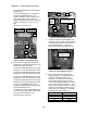
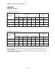
Auxiliary Connection
Figure 2 : Motor Contactor Connections
9. Using a flat screwdriver, 3mmx100mm
(1/8”x4”), torque the following auxiliary
terminals to 2.0 N-m (17.5 in-lbs) on the
right side of the motor contactor. See
Figure 28 for location of auxiliaries.
Wire Number
AJ9CC1-2 31
AJ9CC1-4 32
8
7
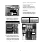
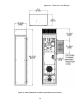
Torque the motor terminals and ground
terminals to 31.0 N-m (275 in-lbs) using a
8mm (5/16”) Allen hex key.
Tie wrap the two rubber boots to the output
terminal blocks A1 and A2 after wiring the
motor armature.
Figure 2 : Right side of Motor Contactor
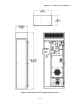
10. For Motor Armature Connections, place
rubber boots over wires first, then connect
those appropriately sized wires from the
motor armature directly to the motor
contactor (ME) compression lug terminals
(1) and (3). Also connect a properly sized
frame to t ground continuity wire from the
motor he PE grounding terminal on the
Motor Side drive panel. See EMC
Compliance on page 9 .
26 25 16 19
TB2-1
To motor
contactor
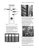
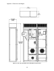
11. Finally, connect the incoming 3-phase
power wires and PE building ground to the
main power terminals at the top of the Line
Side Converter enclosure. View Figure 29
for locations of terminals.
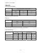
Use the following torque specs when
tighten the screws and lugs down:
Wire References Torque Specs
Power Terminals 56.6 N-m (500 in-lbs)
Plastic Cover Screws 0.23-0.28 N-m (2-2.5 in-lbs)
Ground Terminals 31.0 N-m (275 in-lbs)
9
Incoming
Power
T
e
rmin
a
l
s
Grounding
lug
Plastic
Safety
Cover
#A9JCC1-2 to 31
#A9JCC1-2 to 32
Figure 2 : Power Terminals
101