
Computer Hardware User Manual
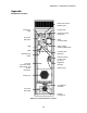
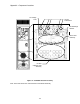

Appendix – Component Locations
0
1
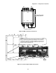
15(+)3
246(-)
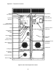
A1 A2
Optional Dynamic
Braking Resistor
To Motor Inverter
Figure 4 : Motor Contactor Connections
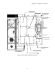
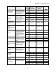
TB1
TB2
RS422
TB1-25
TB1-1
TB1-48
TB1-24
TB2-8
TB2-14
TB2-1
TB2-7
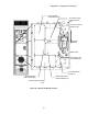
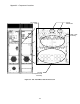
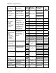
One of the troubleshooting tools provided by Quattro DC, is the
ability to view the Logic Inputs and Outputs by use of the LEDs on
the Customer I/O Board. The LED lit indicates a Logic Input of 1.
This does not take into consideration whether the input is set as
Normal Closed (see Submenu C2).
Logic
Input 1
Logic
Input 9
Logic
Output 1
Logic
Output 7
Figure 4 : Customer Input / Output Connections
115