
Computer Hardware User Manual


Quattro DC Startup Guide
Quattro startup guide
Initial Inspection
Unpacking
1. When unpacking, check drive for any
shipping damage.
2. The 200A and 250A versions of the
Quattro arrive in separate shipping
containers, which require connection in the
field. Prior to connecting enclosures,
check serial numbers on each cabinet
section to insure mating compatible units.
Proper mating of enclosures and wiring
between is important. Refer to the re-
connection instructions on page 98.
3. Review the technical manual, shipped with
the drive.
4. Verify the proper drive model numbers and
voltage ratings as specified on the
purchase order.
5. Location of the Quattro is important for
proper operation of the drive and normal
life expectancy.
Installation
The installation should comply with the
following:
− DO NOT mount in direct sunlight, rain or
extreme (condensing) humidity.
− DO NOT mount where corrosive gases or
liquids are present.
− AVOID exposure to vibration, airborne dust
or metallic particles.
− DO NOT allow the ambient temperature
around the control to exceed the ambient
temperature listed in the specification.
Observe the following precautions:
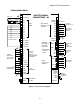
1. Wiring guide lines
For Logic Input and Output I/O
connections, use quality, multi-
conductor cable or discrete stranded
wire only.
For Encoder and Analog I/O
connections, use quality, multi-
conductor braided shield cable*.
For Communication I/O connections,
use quality, multi-conductor braided
shield* cable or twisted pair wire.
*Cable shields to be terminated with a 180/360
degree metal cable clamp attached to Control
Tray panel flange. Refer to the EMC
Compliance on page 97.
2. Never connect main AC power to the
output terminals
3. Never allow wire leads to contact metal
surfaces. Short circuit may result.
4. SIZE OF WIRE MUST BE SUITABLE FOR
CLASS I CIRCUITS.
5. Motor lead length should not exceed 20m
(60 ft). If lead length must exceed this
distance, contact Magnetek for proper
installation procedures.
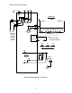
6. The following are required to be contained
in individual conduit runs: 3-phase
incoming power, control power, DC
armature wires, and DC shunt field.
7. Use UL/CSA certified connectors sized for
the selected wire gauge. Install
connectors using the crimping tools
specified by the connector manufacturer.
8. Control wire lead length should not exceed
20m (60 ft). Signal leads and feedback
leads should be run in separate conduits
from power and motor wiring.
9. Verify that the input voltage matches the
drive’s rating.
10. Verify that the motor is wired for the
application voltage and amperage.
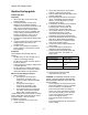
11. Tighten all of the three-phase power and
ground connections. See Table 1 for
torque specs.
Wire References Torque Specs
Power Terminals 56.6 N-m (500 in-lbs)
Plastic Cover Screws 0.23-0.28 N-m (2-2.5
in-lbs)
Ground Terminals 31.0 N-m (275 in-lbs)
Table 1: Input Power Torque Specs
12. Check that all control and signal
terminations are also tight.
CAUTION: TO PREVENT DAMAGE TO THE
DRIVE. THE FOLLOWING CHECKS MUST
BE PERFORMED BEFORE APPLYING THE
INPUT POWER.
− During shipping, connections may loosen;
inspect all equipment for signs of damage,
loose connections, or other defects.
− Ensure the three-phase line voltage is
within ±10% of the nominal input voltage.
Also verify the frequency (50 or 60 Hz) is
correct for the elevator control system.
− Remove all shipping devices.
− Ensure all electrical connections are
secure.
− Ensure all transformers are connected for
proper voltage.
12