
Computer Hardware User Manual
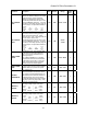

Quattro DC Drive Parameters A1
33
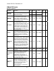
Parameter Description Units Default Range
Hidden
Item
Run
lock
out
EXT TORQUE
BIAS
(External Torque Bias) This parameter
subtracts an effective voltage to the actual
analog pre torque / torque command
(channel 2) voltage signal. Note: Drive
automatically limits current at 300% or the
value in CURRENT LIMIT (A1). For more
information, see Analog Inputs on page 18
and Pre-Torque / Torque Feed Forward on
page 23.
uses
software
drive
signal
MULT
TORQUE
EXT
BIAS
TORQUE
EXT
voltage
input
channel#2
analog
=×
⎟
⎟
⎟
⎠
⎞
⎜
⎜
⎜
⎝
⎛
−
volts 0.00 -6.00 – +6.00
Y Y
EXT TORQUE
MULT
(External Torque Multiplier)
This
parameter scales the analog pretorque /
torque command (channel 2). If this
function is set to 1.00, a 10V signal will call
for 100% torque. Note: Drive
automatically limits current at 300% or the
value in CURRENT LIMIT (A1). For more
information, see Analog Inputs on page 18
and Pre-Torque / Torque Feed Forward on
page 23.
uses
software
drive
signal
MULT
TORQUE
EXT
BIAS
TORQUE
EXT
voltage
input
channel#2
analog
=×
⎟
⎟
⎟
⎠
⎞
⎜
⎜
⎜
⎝
⎛
−
none 1.00
-10.00 –
+10.00
Y Y
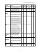
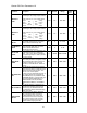
ZERO SPEED
LEVEL
(Zero Speed Level)
This parameter sets
the threshold for zero speed detection.
This is only used to generate the zero
speed logic output.
Note: if DIR CONFIRM (C1) is enabled,
this parameter also sets the threshold for
the termination of the test to confirm the
polarity of the analog speed command.
Unites in percent of contract speed
% 1.00 0.00 – 99.99
Y Y
ZERO SPEED
TIME
(Zero Speed Time)
This parameter sets
the time at which the drive is at the ZERO
SPEED LEVEL (A1) before zero speed
logic output is true.
sec 0.10 0.00 – 9.99
Y Y
UP/DWN
THRESHOLD
(Directional Threshold)
This parameter
sets the threshold for the direction sense
logic outputs. If speed feedback does not
reach this level, the drive will not detect a
directional change. This is only used to
generate the direction sense logic outputs
(car going up and car going down). Units
in percent of contract speed.
% 1.00 0.00 – 9.99
Y Y
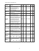
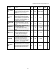
ANA OUT 1
OFFSET
(Digital to Analog #1 Output Offset)
Offset
for scaling Analog Output Channel #1.
voltage
output
channel
analog
GAIN
OUT
ANA
OFFSET
OUT
ANA
creates
software
drive
signal
=×
⎟
⎟
⎟
⎟
⎟
⎠
⎞
⎜
⎜
⎜
⎜
⎜
⎝
⎛
−
% 0.0 -99.9 – 99.9
Y N
ANA OUT 2
OFFSET
(Digital to Analog #2 Output Offset) Offset
for scaling Analog Output Channel #2.
voltage
output
channel
analog
GAIN
OUT
ANA
OFFSET
OUT
ANA
creates
software
drive
signal
=×
⎟
⎟
⎟
⎟
⎟
⎠
⎞
⎜
⎜
⎜
⎜
⎜
⎝
⎛
−
% 0.0 -99.9 – 99.9
Y N