
Computer Hardware User Manual
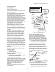
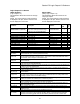
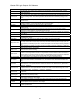

Quattro DC User Switches C1
Detailed descriptions
HI/LO GAIN SRC
(High / Low Gain Source)
This parameter determines the source of the
high / low gain switch.
The speed regulator high / low gain function
was developed in response to high
performance elevator requirements where the
resonant nature of the elevator system
interferes with the speed response of the drive.
When the speed response (gain) is set to high
levels, the resonant characteristics created by
the spring action of the elevator ropes can
cause car vibration. To solve this problem, the
speed regulator is set to a low enough
response (gain) so that the resonant
characteristics of the ropes are not excited.
This is accomplished by controlling the
sensitivity or response of the speed regulator
via the high / low gain switch and gain reduce
multiplier.
By using the gain reduce multiplier, the user
can specify a lower response (gain) for the
speed regulator when the drive is at higher
speeds. The gain reduce multiplier (GAIN
REDUCE MULT(A1)) tells the software how
much lower, as a percentage, the speed
regulator response (gain) should be.
The high / low gain switch determines when
the drive is in ‘low gain’ mode. In the ‘low gain’
mode, the gain reduce multiplier has an effect
on the speed regulator’s response (gain).
The drive allows for the high / low gain switch
to be controlled either externally or internally.
The high / low gain source parameter (HI/LO
GAIN SRC) allows for this external or internal
selection.
The high / low gain switch can be controlled
externally by either:
• a logic input
• the serial channel.
The high / low gain switch can also be
controlled internal by:
• the gain change level parameter (GAIN
CHNG LEVEL), which defines a
percentage of contract speed.
With the drive set to internal control, the speed
regulator will go into ‘low gain’ mode when the
drive senses the motor is above a defined
speed level. The defined speed level is
determined by the gain change level
parameter.
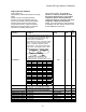
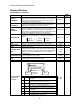
An example of internal high / low gain control
is shown below.
High / Low Gain Example
Elevator Speed Regulator (Ereg)
The use of the Elevator Speed Regulator
allows the overall closed loop response
between speed reference and speed to be
ideal for elevator applications. The desirable
features of the Elevator Speed Regulator are:
• no overshoot at the end of accel period
• no overshoot at the end of decel period
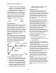
One characteristic of the Elevator Speed
Regulator is that during the accel / decel
period the speed feedback does not match the
speed reference creating a speed error or
tracking delay. As an example, the Elevator
Speed Regulator’s speed response is shown
for a ramped speed reference below.
speed
feedback
speed error
trackin
g
dela
y
speed
reference
commanded
s
p
eed
no
overshoot
time
s
p
eed
0%
contract
speed
low gain
mode
Response of
Speed
Regulator
8.0 rad/sec
10%
contract
speed
10%
contract
speed
Response of
Speed Regulator
8.0 rad/sec
HPV 900 Parameter Settings
HI/LO GAIN SRC = internal
GAIN REDUCE MULT = 80%
GAIN CHNG LEVEL = 10 %
RESPONSE = 10.0 rad/sec
Response of
Speed Regulator
10.0 rad/sec
0%
contract
speed
Response of
Speed Regulator
10.0 rad/sec
speed
reference
100%
contract
speed
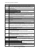
Ereg Example
The Elevator Speed Regulator is tuned by:
• System Inertia parameter (INERTIA(A1)),
which is easy to obtain by using the drive
software to estimate the system inertia.
59