PORTABLE GENERATOR MPG 3800 OPERATING/PARTS MANUAL
This manual provides information and procedures to safely operate and maintain the engine and generator. For your own safety and protection from physical injury, carefully read, understand, and observe the safety instructions described in this manual. The information contained in this manual was based on machines in production at the time of publication. Magnum Products LLC reserves the right to change any portion of this information without notice.
TABLE OF CONTENTS Page INTRODUCTION .............................................................................................................................. 2 TABLE OF CONTENTS ................................................................................................................... 3 SAFETY NOTES ............................................................................................................................. 4 OPERATING SAFETY .....................................................
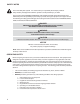
SAFETY NOTES This is the safety alert symbol. It is used to alert you to potential personal injury hazards. Obey all safety messages that follow this symbol to avoid possible injury or death. This manual contains DANGERS, WARNINGS, CAUTIONS, NOTICES and NOTES which must be followed to prevent the possibility of personal injury or death, damage to equipment, or improper service.
ENGINE SAFETY Internal combustion engines present special hazards during operation and fueling! Failure to follow the safety guidelines described below could result in severe injury or death. Read and follow all safety warnings described in the engine operator’s manual. A copy of this manual was supplied with unit when it was shipped from the factory. • DO NOT run engine indoors or in an area with poor ventilation unless exhaust hoses are used.
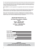
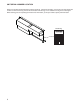
UNIT SERIAL NUMBER LOCATION Refer to the location illustrated below to find the unit ID tag. Important information, such as the unit serial and model number are found on this tag. Record the information from this tag, so it is available if the tag is lost or damaged. When ordering parts or requesting technical service information, you may be asked to specify this information. Unit ID Tag 215 Power Drive • Berlin, WI 54923 1-800-926-9768 MODEL MPG 3800 SERIAL NUMBER 000000 lbs. kg amb. temp.
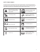
SAFETY SYMBOL SUMMARY This equipment has been supplied with numerous safety and operating decals. These decals provide important operating instructions and warn of dangers and hazards. Replace any missing or hard-to-read decals and use care when washing or cleaning the unit. Decal placement and part numbers can be found in the parts section of this manual. Below is a summary of the intended meanings for the symbols used on the decals.
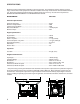
SPECIFICATIONS Read this manual carefully before attempting to use this generator. The potential for property damage, personal injury or death exists if this equipment is misused or installed incorrectly. Read all of the manuals included with this unit. Each manual details specific information regarding items such as set-up, use and service requirements. SPECIFICATIONS ARE SUBJECT TO CHANGE WITHOUT NOTICE. MAGNUM MODEL MPG 3800 Generator Specifications Generator Frequency .................................
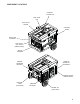
COMPONENT LOCATIONS CENTRAL LIFTING EYE FUEL TANK CAP FUEL LEVEL GAUGE CONTROL PANEL AIR FILTER HOUSING FUEL SHUT OFF VALVE (UNDER TANK) RECOIL STARTER HANDLE WHEEL KIT (OPTIONAL) ENGINE STARTING BATTERY ENGINE CHOKE (UNDER TANK) BATTERY TRAY (OPTIONAL) ENGINE EXHAUST WHEEL KIT (OPTIONAL) 9
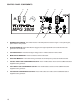
CONTROL PANEL COMPONENTS A B C E D GROUND FAULT SENSING MODULE P O W E R F A U L T RESET RESET WARNING TEST BEFORE EACH USE SEE INSTRUCTIONS MPG 3800 F G H A. ENGINE START SWITCH: This switch must be in the ON position to start the engine. To stop the engine, place switch in OFF position. B. AUTO IDLE SWITCH: When this switch is engaged, the engine speed will return to idle whenever the generator is not under load. C.
GROUNDING THE GENERATOR The National Electrical Code (NEC) requires that the generator be properly connected to an approved ground source. The ground connection for this unit is located on the generator support leg. CONNECTING ELECTRICAL LOADS Allow the engine to warm-up before connecting any devices to the unit. Connect the desired 120 or 240 volt AC, single phase, 60 Hz electrical loads.
WATTAGE CONSUMPTION OF EQUIPMENT DEVICE APPROXIMATE RUNNING WATTS Air Conditioner (12,000 BTU)** ........................................................................................................................... 1700 Air Conditioner (24,000 BTU)** ........................................................................................................................... 3800 Air Conditioner (40,000 BTU)** .............................................................................................
EXTENSION CORD SELECTION CHART MAXIMUM CABLE LENGTH (FT) CURRENT LOAD IN VOLTS WATTS (AMPS) 5 600 120 10 1200 120 15 1800 120 20 2400 120 240 240 240 240 #10 225 115 75 57 455 225 151 110 #12 140 70 47 36 #14 90 285 45 140 30 95 70 #16 180 60 - 90 60 - 120 - Keep extension cords as short as possible, preferably less than 15 feet long, to prevent voltage drop and possible overheating of wires.
STARTING THE ENGINE WARNING Never start or stop engine with electrical devices plugged into the receptacles AND devices turned on. 1. Unplug all electrical loads from the unit’s receptacles before starting the engine. 2. Make sure the generator is on a firm, level surface, away from any overhangs, open windows, vents or doors. 3. Check the fuel and engine oil levels. 4. Turn the main circuit breaker off. 5. Open the fuel shut-off valve. 6. Turn the engine start switch on. 7.
STOPPING THE ENGINE 1. Shut off all loads and unplug electrical loads from the control panel receptacles. WARNING Never start or stop the engine while electrical devices are plugged in and turned on. 2. Turn the idle control switch off. 3. Switch the main circuit breaker to the off position. 3. Let the unit run for 3-5 minutes with no load to allow stabilization of the internal temperatures of the engine and generator. 4. Turn the unit off. 5. Close the fuel shut-off valve.
MAINTENANCE SCHEDULE The following maintenance schedule should be followed to ensure proper performance of the unit. ITEM DAILY Visual walk around inspection Check engine oil level Check air filter Change engine oil Clean air filter Check and adjust spark plug Clean muffler/spark arrester Replace spark plug 20 HRS. 50 HRS. * 100 HRS. Check and adjust idle speed Check and adjust valve clearance Replace air filter Clean combustion chamber 300 HRS.
UNIT DECALS 2 1 3 G 4 5 1 2 3 ON ON OFF OFF CHECK FUEL ON CHECK OIL MAIN BREAKER OFF ENGINE SWITCH ON TURN FUEL ON MAIN BREAKER ON OFF MAIN BREAKER OFF ENGINE SWITCH OFF TURN FUEL OFF PN: 26560 Magnum Red Stripe - PG GFCI TESTING INSTRUCTIONS TEST BEFORE EACH USE! GROUND FAULT SENSING MODULE P O W E R F A U L T RESET R ESET WARNING TEST BEFORE EACH USE SEE INSTRUCTIONS Normal operating state - sensing device green led is “on” and circuit breaker is at “on” position.
CONTROL PANEL ASSEMBLY 17 1 8 TO FRAME 13 16 9 7 6 20 5 20 15 12 18 9 4 11 14 19 11 3 10 18 2 18
ITEM NO. PART NO. 1 2 3 4 5 6 7 8 9 10 11 12 13 14 15 16 17 18 19 20 26213 24986R 65888 65878 65487 65942 65886 65941 26233 60398 60181 60091 60051 65874 65873 19211 60161 60046 60728 60061 QTY 1 1 2 1 1 1 1 1 1 4 4 4 4 1 1 1 7 5 5 4 DESCRIPTION Panel, control - rear housing Panel, control Receptacle, 120V/20A duplex-black Module, auto idle Receptacle, 120V/30A twist Receptacle, 240V/20A twist Module, GFI sensing Breaker, 16A, 240V Switch, 120V/240V Screw, 10-32X.500 pan phil 316 SS Screw, M3-0.
FRAME AND FUEL TANK ASSEMBLY 2 3 1 4 5 21 6 20 37 18 19 19 27 22 23 7 22 20 19 26 6 28 17 16 15 28 29 13 8 24 6 29 10 12 14 33 11 10 8 32 9 34 30 25 27 13 27 13 35 36 31 20
ITEM NO. PART NO. QTY DESCRIPTION 1 2 3 4 5 6 7 8 9 10 11 12 13 14 15 16 17 18 19 20 21 22 23 24 25 - 26123 26122 28495 28494 60393 60243 24916B 60144 60690 60698 61120 61088 60358 26115 60028 60271 60119 61142 60309 61152 24920B 60307 61147 60168 60095 50380 14216 1 1 1 1 4 9 1 6 2 4 2 2 18 1 2 2 2 2 6 4 1 4 2 1 1 .521 ft. 2 Valve, fuel tank Gauge, fuel tank Cap, fuel tank Tank, fuel Screw, .250-20X1.000 hx hd Washer, flat .250 USS Weldment, frame Nut, .250-20 nylock Screw, .375-16X1.
ENGINE AND GENERATOR ASSEMBLY 2 1 2 1 3 4 5 6 3 9 2 1 36 2 TO FRAME 38 33 39 10 7 39 3 37 TO MUFFLER 35 30 34 18 32 33 31 29 28 18 TO FRAME 11 40 17 27 12 19 26 17 18 13 14 19 15 25 19 18 8 24 22 17 22 24 20 19 TO FRAME 21 23 16
ITEM NO. PART NO. 1 2 3 4 5 6 7 8 9 10 11 12 13 14 15 16 17 18 19 20 21 22 23 24 25 26 27 28 29 30 31 32 33 34 35 36 37 38 39 40 - 60028 60271 61147 24922R 24954 60243 60144 60358 26114BH 60168 61131 26416 26463 26417 26418 26419 60140 60206 60386 15241 60309 60276 60275 60478 24923B 60205 12927 60352 28492 26411 60972 60020 28483 60095 28482 24956BH 24921B 24988 61134 26601 26602 26603 26604 26605 26606 26607 QTY DESCRIPTION 8 10 8 1 1 2 2 2 1 2 4 1 1 1 1 1 4 8 8 1 1 1 1 2 1 2 Screw, .312-18X1.
RD/WT GRN BLU BLU BLU BLK BLK 12 16 15 14 8 4 11 7 3 10 6 2 Y G GRN/YEL W X 120/240 TWIST BLU WHT BLK WHT RED WHT WHT BLK RED BLK G BLK BLK YEL ORN BLK COMMONS 3,7,11,15 120/240 4,8,12,16 W 2 WHT N/O COM 1 LINE 4 LOAD 3 RED BLK X X 120 RECP #1 W WHT W WHT WHT YEL BLK RED WHT WHT BLU BLK RED WHT WIRES MUST BE TWISTED TOGETHER GOING THRU CT X X BLU BLK RED 120 RECP #2 BLK WHT/BLK BLU GRN RED Y 120 ONLY 2,6,10,14 BLK 120 TWIST SEE DC PRINT 4
ORN WHT/BLK IDLE/RUN SWITCH OIL LEVEL SWITCH OIL ALERT UNIT GRN GENERATOR RED GRN BLK IDLE/RUN MODULE BLU ON/OFF SWITCH 4 2 1 COIL ORN 2 3 BLK RED GRY 1 GRY SHUTDOWN SOLENOID WHT/BLK IDLE/RUN SOLENOID START SWITCH RECTIFIER CHARGE COIL + - STARTER DC WIRING DIAGRAM 25
NOTES: 26
REV: A PART NO: 26126 01.18.