Magnum Dynalab MD 108T ANALOG FM TUNER INSTRUCTION MANUAL
-2- TABLE OF CONTENTS A MESSAGE FROM THE PRESIDENT............................................................ 3 UNPACKING YOUR MD 108 T ................................................................... 4 CONTROL FUNCTIONS .............................................................................. 5 FRONT PANEL DISPLAY ............................................................................ 6 INSTALLING THE MD 108 T ......................................................................
-3- A Message From the President Thank you for choosing the Magnum Dynalab “MD 108 T ” Triode FM Tuner, one of our finest FM tuners. Great care has been given in the design, manufacturing and selection of components for the “MD 108 T” Tuner in order to ensure many years of listening enjoyment. The MD 108 T is the culmination of years of research and development. We have expended considerable effort at every phase of the design process to achieve the highest level of performance.
-4- UNPACKING YOUR MD 108 T Carefully inspect all sides of the shipping carton for damage. If there are marks or holes in the carton make note of the location in relation to the unit inside. Any obvious dents or scuff marks should alert you to the possibility of damage. Open the top flaps and carefully lift the transport case out of the carton. Carefully remove the MD 108 T from the end caps and wrapping, inspect all sides.
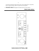
-5- CONTROL FUNCTIONS The front panel controls consist of the following functions (Each function is clearly displayed on the Front Panel Display illustration on the following page): A. POWER: Controls the power to all display functions. All functions are kept in stand-by mode. Any LEDs on the front that are lit will stay lit. B. MUTE: Controls the elimination of inter-station noise. It is recommended that, when receiving marginal signals, the mute be set to off.
-6minimize the shadow (the light green area). Use the Magic Eye in conjunction with the signal strength meter to achieve the best response. L. FREQUENCY DISPLAY: Displays the frequency that you are tuned to.
-7- INSTALLING THE MD 108 T 1. Position the tuner the shortest distance from your preamplifier. Avoid putting the unit where there are extremes in temperature. 2. Remove the AC cord from the pouch on the lid of the carrying case and plug it into the AC receptacle at the rear of the unit. DO NOT PLUG THE CORD INTO THE WALL POWER SOURCE AT THIS POINT. 3. Connect the tuner to your preamplifier using a set of cables consistent with the caliber and type (balanced or unbalanced) of your system.
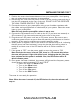
-8- REAR PANEL DISPLAY – INPUTS & OUTPUTS INPUTS (Located at rear of unit): The MD 108 has two antenna inputs, labeled A1 and A2. These are controlled by the front panel input selector knob (Knob on left side of front plate). The inputs D1 and D2 are for future use. OUTPUTS (Located at the rear of the unit): The MD 108 T uses high grade XLR connectors for balanced output in a fully balanced system. Unbalanced output is handled through the high quality gold plated WBT RCA connectors.
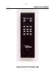
-9- TUNER REMOTE (OPTIONAL) If your tuner was ordered with the RC2 “PRECISION REMOTE SYSTEM”, please reference the following operating instructions. 1. The power switch should be off on the front panel of the tuner 2. Using the remote handheld, push the “POWER ON” button. You will see the tuner turn on. YOU MUST TURN THE POWER ON MANUALLY ON THE FRONT PANEL TO TUNE IN MANUAL MODE. IF YOU TURN THE POWER ON WITH THE REMOTE CONTROL YOU WILL BE IN REMOTE TUNER MODE. 3.
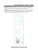
- 10 - IMAGE OF RC2 REMOTE
- 11 - TROUBLESHOOTING PROBLEM No sound, meter lights are not on No sound, meter lights are on Signal strength is low Reception is poor POSSIBLE CAUSE • Power cord disconnected • Power off at source • Fuse blown • Interconnect not properly installed • Preamp set to wrong source • Bandwidth switch not activated • Power amp off • Tube failure • Antenna not connected • Wrong type of antenna • • Station too far away Antenna pointed the wrong way • • • Antenna not connected Wrong type of antenna Cross t
- 12 - RECEPTION TECHNIQUES Antenna Cabling: The lead-in cable from the antenna is often the weakest link in the FM system. Some time spent on selection and matching will yield dramatic results when it comes to noise reduction in weak signals. A good grade of 75 ohm coaxial cable will provide very sufficient signal passage, along with effective shielding against interference. Without effective shielding your coaxial cable can in fact become an antenna in itself.
- 13 outdoors, but regardless of whether it is installed indoors or outdoors the higher that you can put it the better it will perform. Magnum Dynalab offers the MD ST-2, an excellent vertical ½ wave antenna Folded Di-Pole - This is the most common and simplest of all antennas, most people are familiar with the 79 cent piece of wire you received with most electronics gear (generally provided with a tuner or receiver).
- 14 - PRODUCT SPECIFICATIONS Usable sensitivity- Mono – 50 dB quieting – Mono – 50 dB quieting – Stereo – Capture ratio – Image rejection – Signal to noise ratio – Alternate channel – Wide – Alternate channel – Narrow Alternate channel – Super narrow – Adjacent channel – Wide – Adjacent channel – Narrow Adjacent channel – Super Narrow – THD – Mono – THD – Stereo – Stereo separation – AM suppression – SCA rejection – IF rejection – 19 KHz and 38 KHz component rejection – Audio frequency response (+/- 1 dB
- 15 - SAFETY SHEET IMPORTANT SAFETY INSTRUCTIONS 1. 2. 3. 4. 5. 6. KEEP THESE INSTRUCTIONS HEED ALL WARNINGS FOLLOW ALL INSTRUCTIONS DO NOT USE THIS APPARATUS IN WATER CLEAN ONLY WITH DRY CLOTH DO NOT BLOCK ANY VENTILATION OPENINGS, INSTALL IN ACCORDANCE WITH THE MANUFACTURER’S INSTRUCTIONS. 7. DO NOT INSTALL NEAR ANY HEAT SOURCES SUCH AS RADIATORS, HEAT REGISTERS, STOVES, OR OTHER APPARATUS (INCLUDING AMPLIFIERS) THAT PRODUCE HEAT. 8. DO NOT DEFEAT THE SAFETY PURPOSE OF THE GROUNDING TYPE PLUG.
- 16 - LIMITED WARRANTY Register your product at www.magnumdynalab.com Magnum Dynalab Ltd. herein referred to as the “manufacturer” guarantees this product to be free of defect in both material and workmanship and agrees to remedy any such defect or replace any defective component at no charge for a period of two years from date of sale to the first end user.