
PT-100 Manual


© 2017 Sensata TechnologiesPage 10
Installation
2.3.5 Ventilation and Clearance Requirements
The charge controller should not be installed in an area that allows dust, debris, insects or rodents
to enter or block the controller’s ventilation openings, or in an area without suffi cient air flow
around the PT’s enclosure. There must be free air movement through the controller and over the
controller’s rear heatsink fi ns. This is done by mounting on the side of a Magnum Panel (see Figure
2-8 or by using the supplied wall-mounting bracket to mount against a wall (see Figure 2-10).
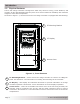
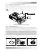
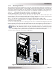
The PT-100 controller uses two fans to force air through the controller to help maintain the proper
internal operating temperature. The fans pull in air through the intake vents and blow out air through
the exhaust vents (see Figure 2-6). In order for the PT-100 to provide full output power and to
avoid over-temperature fault conditions, do not cover or block the ventilation openings or install
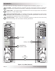
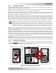
this charge controller in an area with limited airfl ow. When mounting the controller, ensure there is
free air fl ow through the controller and adequate clearance around the rear heatsink fi ns. To provide
adequate ventilation, allow at the minimum, a clearance of 6” (15 cm) from the bottom surface and
1” (2.5 cm) from the rear and at least 1” (2.5 cm) from one of the side surfaces (see Figure 2-7).
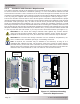
CAUTION: Do not mount this charge controller fl ush against any surface without
using the wall-mounting bracket that is provided. Damage to the surface and over-
temperature shutdowns may occur, and service life of the controller may be affected.
CAUTION: Do not mount this charge controller in a zero clearance compartment, nor
cover or obstruct the ventilation openings—overheating will result.
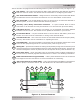
Info: If required, the controller may be installed in an enclosure, as long as it is
ventilated with suffi cient air flow. The enclosure must have a fresh air intake opening
provided directly to the side of the controller close to the intake vents and an exhaust
opening close to the exhaust vents on the charge controller. This allows cool air from the
outside to fl ow in and heated air to exit out of the PT-100 and the enclosure.
Figure 2-7, Minimum Mounting
Clearance Requirements
BOTTOM
at least 6"
(15 cm)
REAR
(and at least
one side)
at least 1"
(2.5 cm)
REAR SURFACE
BOTTOM SURFACE
PT-100
Charge
Controller
(side view)
Figure 2-6, Air Flow in and around PT
Air intake
vents
Air exhaust
vents