
PT-100 Manual


Page 13
© 2017 Sensata Technologies
Installation
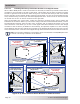
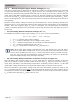
2.3.6.2 Mounting the Charge Controller on a Vertical Surface
The PT controller is shipped with a bracket that consists of two identical plastic pieces. When these
two pieces are connected together, they provide a complete wall-mounting bracket that allows the
PT-100 to be mounted to a vertical surface (wall)—providing the required minimum 1” (2.5 mm)
airfl ow clearance behind the controller. Refer to Figure 2-13 for bracket dimensions.
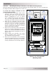
Info: The hardware to mount the PT controller to the bracket is provided. The hardware
to secure the wall-mounting bracket to the wall is not supplied. It is recommended to
use #8 sized (M5) fasteners. However, because mounting surfaces can vary, installers
must determine the appropriate hardware for the installation. The surface and mounting
hardware must be capable of supporting at least twice the weight of the charge controller
(12.5 lb/5.7 kg), as well as the associated wiring/conduit.
W
W
W
W
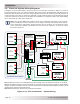
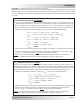
PT Controller
Mounting Holes
(Ø.120 Thru Holes x 4)
P1
Wall/Surface
Mounting Holes
(Ø.180 Thru Holes x 12)
W
P1P1
P2
P2
P2
and
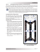
Installing the Wall-mounting Bracket
After determining the proper mounting location,
use the following steps to mount the PT controller
on a wall or a similar fl at upright surface with the
two-piece mounting bracket (refer to Figure 2-12 to
ensure a secure mounting).
To secure the wall-mounting bracket to a
vertical surface:
1. Use one of the bracket pieces for the bottom
half of the bracket and hold it on the mounting
surface at the desired height. While using a
level to ensure it is horizontally and vertically
straight (and the openings in the bracket are
faced toward the top), insert two #8 sized
screws into any of the wall mounting holes
(designated as “W” in Figure 2-10).
2. Now that the bottom bracket is mounted,
use the other bracket piece as the top half
and insert it into the openings of the bottom
bracket. While holding the top bracket in
place, insert two #8 sized screws into any of
the designated “W” wall mounting holes (see
Figure 2-10).
3. Insert screws into the remaining wall mounting
holes (“W”) and ensure the bottom and top
bracket pieces are fi rmly attached to the
mounting surface.
Figure 2-10, Mounting Bracket
Thru-hole Callouts